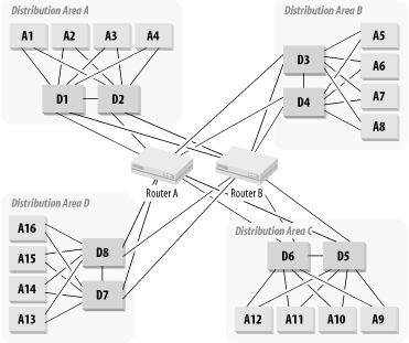
Figure 3-24. A hierarchical network with central routing
There are three main options for large-scale topology. If you want to use VLANs, and their benefits should be clear by now, then you need to have routers to interconnect them. Your options basically come down to where to put these routers. You can put them in the Core or in the Distribution Level, or you put them in both. It is usually best to avoid putting routers at the Access Level of a LAN, but for very large networks it is easy to see that you get much better scaling properties if you include routers in the Distribution Level.
Perhaps the simplest and most obvious way to build a large-scale hierarchical network is to use a model like that shown in Figure 3-24. In this diagram, several different Distribution Areas are connected via a central Routing Core consisting of two routers. All Distribution Areas are redundantly connected to both Core Routers from both Distribution switches.

The result of all these redundant connections is that any device in the Core or Distribution Levels can fail without affecting network operation. Each Distribution Area has redundant Distribution switches, either of which can act as a Root Bridge for this area. Both Distribution switches have connections to both of the two Core routers. If either Core Router fails, you have complete redundancy.
The best part of the redundancy in this network is its simplicity. There are only two central routers (there may be additional routers connecting to remote sites, as I will discuss shortly), and either can quickly take over all central routing functions in case the other fails. Because of the way that these routers are connected to one another and to all Distribution switches, they can both be used simultaneously. However, the extent to which these routers share the load depends on how the dynamic routing protocols are configured.
The limitation to this design is the capacity of one of the Core Routers. You must configure these two routers so that either is able to support the entire network load in case the other fails. So Figure 3-25 shows a simple way of overcoming this limitation. It still has a central routing Core, but now there are four routers in the Core. Each pair of routers is responsible only for a small part of the network.
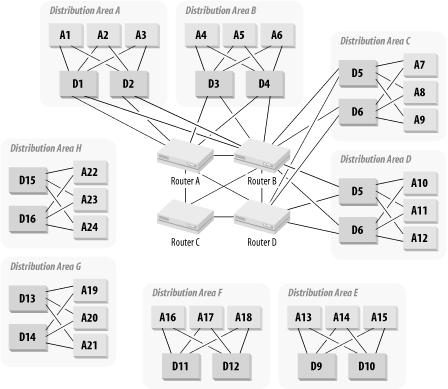
There are many different ways to connect such a Core. Figure 3-25 shows a Core with four routers that are interconnected with a full mesh. I have already indicated that a full mesh does not scale well, so if the network will need further expansion, full mesh would not be a good option. Figure 3-26 shows a similar network but with six central routers connected to one another by a pair of central switches.
Note that there need be no VLANs defined on these two switches. Both switches S1 and S2 have connections to all six routers. A natural way to define the IP segments on these switches is to have one switch carry one subnet and the other carry a different subnet. Then if either switch fails, the dynamic routing protocol takes care of moving all traffic to the second switch.
In this sort of configuration, it is generally useful to make the routers act in tandem. Assuming that Distribution Areas consist of two Distribution switches and several Access switches, you would connect both switches to both routers in this pair, and you can connect several Distribution Areas to each pair of routers. The actual numbers depend on the capacity of the routers. All connections will be fully redundant. Then only the Distribution switches that are part of this group of Distribution Areas will connect to this pair of routers. The next group of Distribution Areas will connect to the next pair of Core Routers.
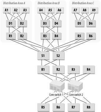
There are two ways to bring the routers into the Distribution Level. One is to simply extend the concept shown in Figure 3-26 and arbitrarily proclaim that the two central switches S1 and S2 are now the Core and the routers are all in the Distribution Level. The distinction between "Core" and "Distribution" Levels is somewhat vague and depends partially on where you draw the lines. One problem with this way of drawing the lines is that these routers interconnect different Distribution Areas, so it is a little tenuous to claim that they are part of the Distribution Level.
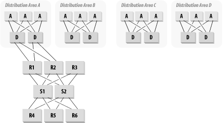
The second way of bringing routers into the Distribution Level is to have one (or preferably two, for redundancy) router for each Distribution Area. This option is shown in Figure 3-27.
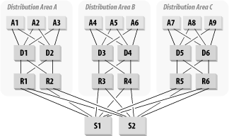
One advantage to this approach is that it provides a very natural application of Layer 3 switching. Each Distribution switch could contain a Layer 3 switching module. This way, you can provide efficient VLAN-to-VLAN communication within each Distribution Area. You would then construct two additional VLANs on each Distribution switch that would connect to the two central switches.
In this sort of model, where routing functions are downloaded to the Distribution Level, another sort of efficiency can be used. Since how you decide which VLANs comprise a VLAN Distribution Area is somewhat arbitrary, you can deliberately choose your areas to limit traffic through the Core. This may not always be practical, particularly if the Distribution Areas are selected for geographical reasons. If it can be done, though, it may radically improve the network performance through the Core.
It's pretty clear that the network shown in Figure 3-27 has good scaling properties, but there are limits to even this model. In Chapter 6, I will discuss the IP dynamic routing protocol called OSPF. This protocol allows IP routers to keep one another informed about how best to reach the networks they are responsible for. There are other dynamic routing protocols but OSPF is an open standard and an industry norm. The comments that follow turn out to be applicable to most of the alternatives as well.
In Figure 3-27, all of the routers talk directly to one another through the Core switches. In any dynamic routing protocol, every router must know about all of its neighboring routers. It maintains a large table of these neighbor relationships and has to keep it continuously up to date. The more neighbors it has, the harder this job becomes, with similar scaling properties to a fully meshed network. The usual rule is that you never want more than 50 routers in one OSPF area. There are exceptions to this rule, as I will discuss in the section on OSPF, but it is never wise to push it too far.
If you want no more than 50 routers in your Core, then you can have no more than 25 VLAN Distribution Areas, since there are two routers in each area. With a capacity of over a thousand users in each Distribution Area, this is a limit that only large organizations will hit. However, it turns out that it isn't terribly difficult to overcome.
All you need to do is create a hybrid of the two solutions, with routers in the Core and Distribution Layers. Each Core router will handle several Distribution routers to allow excellent scaling properties. Figure 3-28 shows an example of how this hybrid might work. In this figure, the two Core routers that serve the Distribution Areas shown are the OSPF Area Border Routers (ABR) for these Distribution Areas.
There are two other key advantages to this sort of design. First, it makes it extremely easy to spread the Distribution Areas geographically. In fact, you could even make your Core spread physically throughout a campus area, or even across several cities. However, doing so is generally not a good plan. The Core in this case represents our OSPF area 0 (a concept that I will explain in Chapter 6). There can be performance and reliability problems in a network that has its area 0 dispersed over wide area links. These problems can be overcome with careful tuning of OSPF parameters, but it leads to a network Core that has to be monitored very closely. A broken link in the Core could have disastrous consequences.
It is actually simpler to have the Core in a single geographical location and to bring the links to the various Distribution Areas via WAN links.
That point leads to the second advantage. It is very easy to integrate a large WAN into this sort of design, as I will show in the next section.
In all but rare exceptions, if you want to get data to remote locations, it is best to route it. Bridging over WAN links should never be the first choice. Thus, the question becomes, where do you connect the routers for these remote sites into your LAN?
There are three possible types of WAN links that you might be interested in connecting. There might be a few geographically remote sites connecting into your LAN, or you might want to attach a more elaborate branch network. The third option involves connecting to external networks such as the public Internet.
In both of the internal cases, it is best to put these connections on routers, and in both cases you should put these routers as close to the Core as possible. Exactly where you connect them depends on where your other routers are. In the external case, the connection should almost certainly be behind a firewall. The question you need to answer here is where to put the firewall.
For internal networks, including both WANs of minor and major proportions, you have to share dynamic routing information with the existing routers. I assume throughout this discussion that this dynamic routing protocol is OSPF, but again, the comments apply generally to most dynamic routing protocols.
The main difference between the case of the small and large WAN is just one of numbers. A WAN of any size should never be part of the network's OSPF area 0. For a single external site, you might be able to get away with it, so I will briefly discuss the single site case.
The easiest way to treat a single external site is to think of it as a VLAN Distribution Area of its own. If it is a sufficiently important external site, then you might want to allow multiple routers and multiple WAN links. A smaller site might be connected with only a single link, probably with dial backup.
There will be a router on the remote site with some sort of WAN circuit connecting it to a router on the main site. One simple way of connecting this router on the main site is to treat it as just another VLAN router. For the case where routers are connected only in the Core, the easiest method is to connect this WAN router to the Core routers as if it were one of them.
It is generally not a good idea to use the LAN Core router as a WAN router. The requirements for LAN Core routers are different from the requirements for a WAN router. The LAN Core router has to handle a lot of VLANs and has to move packets between similar media as quickly as possible. The WAN router has to buffer data and act as a point of junction between LAN and WAN. It is likely that this role will force you to use different router models, perhaps even from different vendors for these two functions.
In the cases in which the VLAN routers are moved into the Distribution Level, it becomes easier to connect the WAN routers. Then, for either a single-site or a multiple-site WAN, you would connect them as shown in Figure 3-29.
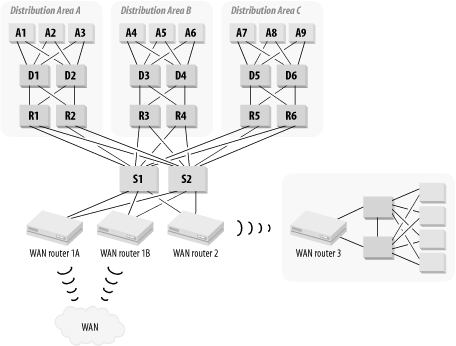
This diagram shows both a single-site and a multiple-site WAN. For the single-site WAN, I assume that the remote site is sufficiently complex to require its own hierarchical network. If it were smaller, then a single switch might be sufficient.
For the multiple-site WAN, the entire cloud is connected to two routers for redundancy. Both routers connect to the LAN Core switches. These new WAN Access routers become members of the OSPF area 0. In the multiple-site case, there will be too many downstream routers to put them all into area 0. This means that the router at the main site must be an OSPF area Border Router. Again, I will explain this concept in more detail in Chapter 6.
The other common way of connecting remote sites uses a WAN Touchdown segment. This segment is simply a separate router-to-router LAN segment or VLAN that only connects WAN routers, as shown in Figure 3-30. In this picture, the Touchdown Segment is created by two redundant routers that connect into the network Core. These routers may be part of the Core, or they may be Distribution Level routers; it all depends on the type of large-scale topology being used.
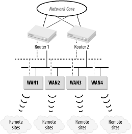
The segment itself is a single VLAN that may be implemented on more than one switch or hub. A single segment like this has an inherent lack of redundancy. However, it can easily be improved by doubling the segment as indicated by the dotted lines.
The Touchdown Segment model for connecting WAN routers to a LAN is a fairly common technique. It has several advantages over connecting the WAN directly to the Core of the network due to the segment being separated from anything internal by means of routers.
First, if there is a requirement for security filtering, then this is a safer method for connecting the WAN. The remote sites may be less trustworthy than the internal network, or they may even be connections to an information vendor's site. In these cases, it is easy to offer basic security support by implementing filtering on the two routers that connect the Touchdown segment or segments to the main network.
Second, WAN links are inherently less reliable than LAN links. It may be desirable to protect the internal network from the effects of unstable links by using these routers as a sort of buffer zone. One of the problems with using a dynamic routing protocol is that flapping links cause all other routers in the area to repeatedly update their routing tables to reflect each change of state. One way to protect against this updating is by using the two routers that connect to the Core as a transition point in the routing protocol. You could run a different routing protocol on the Touchdown segments than you do in the Core, or you could use Border Gateway Protocol (BGP, another routing protocol) on these routers to separate the Touchdown segment's routing protocol from the internal network's routing protocol. BGP will be discussed in Chapter 6.
A third advantage to using Touchdown Segments this way is that it provides an easy expansion method for better scaling. If the Touchdown Segments become congested, building additional segments in the same pattern is relatively easy. If you were connecting each WAN router as a separate Distribution Area, then you would have to think very carefully about its connections to the Core each time. However, with Touchdown Segments, it is much more straightforward to expand the architectural model.
Throughout all of these examples, I have assumed considerable symmetry in the large-scale topology. Although I haven't made a point of discussing this topic until now, it is actually an important feature of a good design. It's important to decide on a global strategy for the network and then follow it. Combining different types of designs doesn't work well.
For example, if your network is large enough to require using routers at the Distribution Level, then all Distribution Areas should have routers. It is certainly reasonable to have a migration plan to do this one area at a time, but this phase is transitional. In the target design, the network should follow consistent rules.
There will always be portions of the network that need to be treated as exceptions. It is generally a good idea to devise a standard method for dealing with exceptions, as I did with the remote sites considered in the previous section. If a few special VLANs require filtering, then they should all be treated with the same technique.
A theme that will repeat throughout this book is simplicity of concept. The benchmark for the appropriate level of simplicity is that an engineer familiar with the network in general should be able to troubleshoot problems on the network without documentation. This rule may sound arbitrary, but any engineer who has been awakened to diagnose network problems over the phone in the middle of the night will immediately recognize its value.
Another key advantage to this level of simplicity is that it allows new staff to learn the system quickly. Building a network that only one genius can understand is a terrible mistake. Sooner or later this genius will grow tired of taking trouble calls and will want to train a successor. Furthermore, a simple network design can also be handed over easily to relatively junior operations staff to manage. This feature has obvious advantages for maintainability, and maintainability is an important key to reliability.