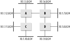
Figure 6-1. Distributing routing information with RIP

One of the oldest dynamic routing protocols used by IP is the Routing Information Protocol (RIP). RIP uses a Distance Vector Algorithm. It should be stressed from the outset that RIP is a poor choice for a large network. I include it in this discussion for two reasons. First, it makes a good introduction for readers who might be unfamiliar with dynamic routing protocols. Second, despite its age, it is still common to encounter specialized pieces of network equipment that support RIP as their only dynamic routing protocol. Integrating these devices into a network requires a good working knowledge of RIP.
There are two common versions of RIP called, appropriately enough, RIP-1 and RIP-2. RIP-1 is the original version introduced during the early days of ARPANET (the spiritual predecessor to the modern Internet) and is documented in RFC 1058, although the protocol was a de facto standard long before this RFC was published. RIP-2 is an updated version of RIP that improves several key operational problems with the original version. The current version of the protocol is documented in RFC 2453.
Although it is often useful in isolated pockets of a network, there are several reasons to avoid using RIP on a network-wide basis. It is slow in responding to topology changes. It is only effective in small- to medium-sized networks and breaks down completely if the distance between any two parts of the network involves more than 15 hops. It can also cause serious traffic-overhead problems in a network with a large number of routes, particularly over slow links.
The original RIP implementation was actually made for UNIX hosts because it effectively predated modern routers. Thus, every BSD UNIX operating system has always been equipped with a program called routed (for routing daemon). This is not merely an interesting quirk of history; it also represents one of the most dangerous problems with running RIP: there are end devices that expect to take part in the routing protocol.
Defenders of the routed argue that it helps these end devices find the appropriate routers for their desired destinations. However, if a network is well designed, it should be possible to simply point all end devices to a single, default gateway address that lets them reach all destinations transparently. In a well-designed network there is never any need to run a dynamic routing protocol on end devices.
End devices don't need to know how the network routes their packets. Letting them take part in the dynamic routing protocol doesn't just give these devices unnecessary routing information. It also allows these end devices to affect the routing protocol, even though they aren't in a position to understand the physical topology of the network.
As a result, it is quite easy for an end device running routed to mislead the network about the best paths. In particular, if the end device is configured with a default gateway, it will attempt to tell the rest of the network about this information. Then if something goes wrong on the network—causing real routes to disappear—the routers will look to the next best option. This often turns out to be the end device that broadcasts the false default route. Since a default route is a route to anywhere, all routing in the network suddenly becomes confused.
In most cases there is a simple way to get around this problem. You can configure the routers that connect to end-device segments so that they ignore all RIP information coming from those segments. This means that you can only use specialized router-to-router segments to carry routing protocol information. These segments cannot contain any end devices.
With RIP an end device can listen passively to routing updates without taking an active role in building the routing tables. This is significantly less dangerous. However, if a network is well designed, there should be no need for any end device to see this information. It should be able to get a packet to any valid destination just by forwarding it to its default router. This default router should respond to topology changes faster and more accurately than the end device. So allowing the end device to make important routing decisions is likely less reliable.
The main idea behind RIP is that every router maintains its own routing table, which it sends to all of its neighbors periodically. The neighbors update their own tables accordingly. Every route in the table has a cost associated with it, which is usually just the number of hops to the destination.
Figure 6-1 has a small network containing four routers and eight Ethernet segments. Router A knows about the two routes directly connected to it: 10.1.5.0/24 and 10.1.12.0/24. It also knows that it has two neighboring routers, B and C.

When Router B receives information about these routes from Router A, it adds these routes to its own table. For the routes that Router A indicates are directly connected, Router B has to specify some higher cost.
In RIP this cost is called a metric. By default, the metric just counts the number of hops. Router A uses a metric of 1 for its directly connected networks, so Router B will increment this metric and show the same entries in its routing table with a metric of 2.
At this point, Router B's routing table is shown in Table 6-1. The table lists the routes in numerical order by destination network because the routers generally display them this way. Router B now sends this same information along to Router D. At the same time, all other routers in the network similarly exchange their routing tables. Clearly, it will take a few rounds of updates before Routers C and D have one another's tables.
|
Destination network |
Metric |
Next hop |
|---|---|---|
10.1.5.0/24 |
2 |
Router A |
10.1.6.0/24 |
1 |
Local |
10.1.7.0/24 |
1 |
Local |
10.1.12.0/24 |
2 |
Router A |
When the process is complete, Router A's routing table looks like Table 6-2. Note that Router A doesn't have a direct connection to Router D, which owns 10.1.8.0/24 and 10.1.9.0/24, so it has to direct traffic for these destinations to Router B.
|
Destination network |
Metric |
Next hop |
|---|---|---|
10.1.5.0/24 |
1 |
Local |
10.1.6.0/24 |
2 |
Router B |
10.1.7.0/24 |
2 |
Router B |
10.1.8.0/24 |
3 |
Router B |
10.1.9.0/24 |
3 |
Router B |
10.1.10.0/24 |
2 |
Router C |
10.1.11.0/24 |
2 |
Router C |
10.1.12.0/24 |
1 |
Local |
As long as nothing in the network changes, this routing table remains constant. If something changes, such as a link becoming unavailable, the protocol needs to make it known. To do this, every router sends its current routing table to all of its neighbors every 30 seconds. This update serves two purposes: it allows the routers to ensure that the neighbor routers are all still working, and it makes sure that everybody has the latest routing table.
Suppose the link between Routers B and D suddenly breaks. Router B finds out about this because it stops seeing updates from Router D. But Router B shouldn't react immediately. There may just be a delay or some noise in the network. Perhaps the update message was lost due to congestion caused by a random burst of traffic. There are many reasons why an individual update might not be received. So RIP waits 180 seconds before declaring the routes dead. After the route is considered dead, the protocol will wait another 120 seconds before actually removing it from the table.
This long wait time reflects, in part, the poorer network media available when the protocol was developed. It was not unusual to lose several packets in a row, so the relatively long wait time is a trade-off between wanting to respond quickly to the change in topology and wanting to prevent instability. A busy or noisy link shouldn't cause the routing tables to search continually for new paths. Doing so results in an unstable network.
When a new router is placed on the network, it needs to get a good routing table as quickly as possible. When it first comes up, the router sends out a special request message on all of its active interfaces. Any neighboring routers found on these interfaces respond immediately to this request with a full routing table, rather than waiting for the regular update cycle. The new router integrates this information into its own routing table, adding information about the new routes that are unique to this new device. Then it turns around and updates its neighbors with the resulting routing table, and the neighbors propagate the new routes throughout the network.
Instead of using the default metric just to count hops to a destination, it can be useful to specify higher values for slower links and lower values for higher bandwidth links. In this way, the network tends to prefer the fastest paths, not just the shortest.
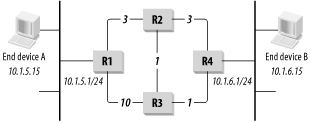
Figure 6-2 shows an example of how this concept might work. Router R1 has connections to both R2 and R3 that can eventually lead it to the destination network, 10.1.6.0/24. The link to R2 is a standard Ethernet connection, and the link to R3 is a 56Kbps point-to-point serial link. The network should favor the faster link, so the Ethernet connection is given a metric of 3 and the serial connection a metric of 10. Similarly, suppose that the connection from router R2 to R4 is Ethernet, so this too will have a metric of 3. The connections between R2 and R3 and between R3 and R4 are Fast Ethernet, though, so these high-speed links will have a metric of 1.

There are four possible paths to get a packet from R1 to the destination network 10.1.6.0/24. It can go from R1 to R2 to R4, with a total metric of six. Or, it can go R1 to R2 to R3 to R4, for a total of five. Similarly, the packet can go R1 to R3 to R4 with a metric of 11. The final possible path is from R1 to R3 to R2 to R4, which has a metric of 14.
So the lowest metric path is the one that goes R1 to R2 to R3 to R4. Because the metric values have been adjusted, the path with the lowest metric is not necessarily the one with the lowest hop count. It is the fastest path, though, which was the point of changing the defaults.
It isn't necessary to give the same metric to all links of a particular type. In fact, you have to be very careful with RIP that you never exceed a total metric of 15 along any valid path. This requirement is too restrictive to establish set rules of different metrics for different media speeds. However this philosophical approach will be quite useful later in Section 6.5.
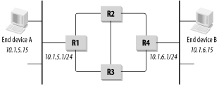
In every dynamic routing protocol, one essential goal is to find the best way to get from A to B. This generally means that every router in the network has to figure out how to get from itself to every place else. Every router has its own routing table that says, regardless of how the packet got here, this is how to get to its ultimate destination. The problem is that, with every device making these decisions on its own, it is possible to wind up with routing loops. Figure 6-3 shows a small network that has four routers. Suppose end device A wants to send a packet to end device B.

A first looks at its own internal routing table for B's address. The destination is not part of its own subnet, so it has to find a route to the destination subnet. Since only one router is on the segment, the end device needs only one default gateway entry in the local routing table. This entry sends everything to router R1.
Now R1 has two options for how to direct the packet. The destination IP address in the packet is 10.1.6.15, so it looks in its routing table for anything that matches this address. There are clearly two possibilities in the picture, R2 and R3. Suppose it sends the packet to R2.
Then R2 must decide how to get to the destination, and it has three possible paths from which to choose: the ones leading to R1, R3, and R4. If everything is working properly, it should see that the path through R4 is the shortest and use that. Suppose it picks one of the others, though—the one through R3, for example. This might happen if a high cost has been assigned to the link to R4, indicating that it is a slow or expensive link.
The routing tables can start to get into trouble because R3 also has three possible paths. Two of these paths, the ones to R1 and R2, send the packet back where it has already been. If R3 chooses either of these paths, it will create a loop.
Fortunately, IP includes a mechanism to break loops like this so that packets do not circulate indefinitely. Every IP packet has a Time To Live (TTL) field in its header. Originally, when network latency was very high, TTL had a real time meaning, but today it is simply a hop counter. In most IP packets the TTL field starts out with a value of 255. Each time a router receives this packet, it decrements the TTL value before forwarding it. If the value eventually reaches 0, the packet is discarded. When I talk about multicast networking in Chapter 10, I discuss another useful application of this TTL field.
You should notice a few important things about routing loops. First, they are fundamentally a Layer 3 phenomenon. It doesn't matter whether the network has multiple connections. A loop could happen if R2 forwarded the packet back to R1 so even if there are no physical loops, a network can still have routing loops.
Also realize that a routing loop happens on a per-route basis. The network might have a loop for one route, say 10.1.6.0, but have no problems with another destination, such as 10.1.5.0. This is different from a Layer 2 loop, which can take all of the traffic into the spin cycle. Every good routing protocol has several techniques for finding and eliminating loops. One of the main ways that RIP avoids loops is by counting to infinity.
The protocol's designers believed that RIP would not converge well in large networks. They estimated that if the distance between any two devices was more than about 15 hops, guaranteeing reliable convergence after a topology change would be difficult. So they somewhat arbitrarily defined infinity as the number 16. This may seem like a small number, but it should be as small as possible if the routers have to count to it quickly.
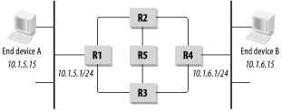
Look at Figure 6-4. Suppose Router R4 suddenly dies and there is no longer any router available for 10.1.6.0/24. The protocol somehow has to flush this route out of the tables of the other three routers.

Routers R2 and R3 will both eventually time out waiting for an update and remove the route they learned from R4. However, Routers R1 and R5 both have routes to get to R4; they can send packets via either R2 or R3.
In the next updates from R1 and R5, R3 will see that they both have routes with a metric of 3 for this destination. R3 will set its own metric to 4 and try to use one of these routes. Meanwhile, R2 will see the same information and do the same thing. Both R2 and R3 will distribute this information back to R1 and R5 in the next cycle.
When R1 and R5 learn that their preferred paths for this destination have suddenly developed higher metrics, they will simply update their own tables, setting the metric to 5. The updated tables are sent back to R2 and R3, which set their metrics for this route to 6 and send it back again. It should be clear why having infinity as small as possible is a good thing. The extinct route will not be removed from the routing table until all routers agree that it is infinitely far away.
RIP has another simple but clever technique for avoiding loops. The protocol stipulates that a router can only send out information about routes that it actually uses. Even if several paths are available, the routers preselect the best one and only worry about the others if this best route becomes unavailable.
For example, look at Figure 6-4 again. Router R2 knows that it can get to the destination network 10.1.6.0/24 through R4. Even though it has heard about alternate routes from both R1 and R3, it never advertises these. Then, when the path through R4 becomes unavailable, it picks either the path through either R1 or R3 and ignores the other.
When R3 also loses its connection with R4, only one possibility remains: R1. However, R1 only advertises the path that it actually uses, which is the one through R2. Eliminating unused—and therefore unnecessary—path options allows the protocol to converge on new paths more quickly when the topology of the network changes.
The triggered update is another important feature of RIP helping it converge more quickly. As I described earlier, all of the routing table exchanges normally happen on a timer. However, when a router's interface physically goes down, the router knows for certain that the associated route is no longer available.
Even with static routes, when this happens the router will flush the corresponding route from its tables. When using RIP, the router follows up on this action by immediately telling its neighbors that this route has disappeared. It does this by telling the other routers that this route now has a metric of 16.
Each time a router changes its metric for a particular route, it also executes a triggered update of this information. This allows the information to propagate through the network quickly.
Meanwhile, another router might still have a connection to this network that had been considered worse because of a higher metric. This new information will propagate through the network as it is now better than the other unavailable route.
The counting-to-infinity example in the previous section might have seemed slightly more complicated than necessary by including router R5 in the middle. But this was necessary because of another clever feature of RIP called Split Horizon that is designed to help destroy loops.
In a regular Split Horizon algorithm, routers simply refrain from passing information back to the router that originally sent it. If R1 and R2 have a link, as they do in Figure 6-4, then R1 will not bother telling R2 about the routes it heard from R2 in the first place.
In fact, RIP employs a slightly modified version of a Split Horizon algorithm called Split Horizon with Poisoned Reverse. To understand this, suppose again that R1 and R2 are sharing routing information. When R1 sends its routing table to R2, it includes the routes it received from R2, but it sets the metric to 16 (remember 16 = infinity in RIP). To see how this causes things to converge faster, the reader is invited to repeat the counting-to-infinity example using the network in Figure 6-3, which is the same as Figure 6-4, but without router R5.
One of the most serious drawbacks with the original RIP specification was how it handled subnets. In Version 1, RIP assumed that all of the subnets for a given network had the same mask. As I already discussed, the ability to vary subnet masks in a complex network is extremely useful. This ability is called Variable Length Subnet Mask (VLSM). It allows not only more efficient use of the address space, but also makes it much easier to summarize the routes to a particular part of the network.
Removing this restriction was a driving force behind the introduction of RIP Version 2. To accomplish this, the protocol had to be modified so that every subnet address could have its subnet mask specified with it. In the original Version 1 specification, the mask information was not included. Consequently, every subnet of any given network was assumed to have the same mask.
This issue is sufficiently serious that it eliminates RIP Version 1 as a candidate routing protocol in most modern networks. However, there are two alternative options. One is to use RIP Version 2 if the equipment supports it. The other, equally viable option, is simply to restrict the use of RIP to small portions of the network where the condition of equal subnet masks can be satisfied.
RIP Version 2 also has the advantage of using multicast rather than broadcast to send its updates. The advantages of multicast are discussed in depth in Chapter 10. In this case it makes it safer to have end devices on the same network segment as routers that communicate via RIP. Because they are broadcast, RIP Version 1 packets must be examined by every device on the network segment. If there are many routers on the network segment, this can cause CPU loading problems on the end devices, even those devices that don't know or care anything about RIP.
In fact, the only reason that RIP Version 1 is ever used in a modern network is for compatibility reasons with legacy equipment. In most of these cases, the RIP routing information is isolated to local communication between the legacy equipment and a modern router. This modern router then redistributes the RIP routes into a more appropriate routing protocol. To allow full two-way communication, this router must also summarize the rest of the network into RIP for the legacy equipment to use.
Another key difference between RIP Versions 1 and 2 is the inclusion of Route Tags. A Route Tag is a two-octet field used to indicate routes that come from outside of the RIP AS. These could come from another IGP or an EGP, or they could even specify routes that are statically configured on a router.
RIP does not use the Route Tag information directly while routing packets, but it is included because it is often useful to know from where different routes came. In other routing protocols Route Tags often ensure that traffic remains inside the AS wherever possible. So, any tagged route will have a higher cost than the worst interior route to the same destination.
This is not practical in RIP, however, because of the small range of allowed metrics. Since any route with a metric of 16 is considered unreachable, it is not possible to use this for exterior routes. The low value of infinity in RIP makes it extremely difficult to balance metrics so as to prefer certain paths to others.
So the Route Tag field is included primarily for information and to allow RIP to pass this information to other routing protocols (in particular, BGP) that can use it.