|
|
|
2.4 ParagraphsA paragraph is a grouping of sentences about a common subject. For example, the English language groups sentences into paragraphs, such as the one you are currently reading. UML paragraphs are diagrams. A diagram is a collection of UML sentences. The elements that make up a diagram are known as diagram elements. For example, all the elements on the figures shown earlier are diagram elements. The main subject about which we communicate is a system that resides in a domain. A domain, also known as a context, is a broad area of interest that has a generally accepted collection of concepts and their relationships. These concepts are classes, and their relationships are associations; both are known as domain elements. For example, the project management system may be used to manage projects in various industries, including product manufacturing, strategic services, financial services, information technology consulting, and so forth, and each industry is a different domain. Understanding a user's domain is critical as a launching point for developing a system that the user and other stakeholders (those having a stake or interest in the project) will find useful and valuable. A system is a collection of elements organized together for a specific purpose. These elements are known as system elements. To understand a system, we focus on its architecture. The architecture of a system involves the elements that make up the system and the way they work together to provide the functionality of the system. The major elements that make up a system are known as architectural elements. A system's elements and their relationships define the system's structure, and the way the elements interact and collaborate define the system's behavior. A system may be recursively decomposed into smaller systems, called subsystems and primitive elements. Subsystems may be further decomposed into sub-subsystems and primitive elements, and so forth. When fully decomposed, a system and all its subsystems consist of primitive elements. Primitive elements cannot be further decomposed. For example, the project management system can be decomposed into the following:
When the primitive elements of a system or subsystem are objects, the system is considered an object-oriented system. When the primitive elements are simply data elements and functions or procedures, the system is considered a non-object-oriented system. The UML provides various modeling techniques for communicating using diagrams. Each type of diagram emphasizes something about a system, and any number of diagrams may be used to communicate about a system. The next sections introduce these diagram types using the project management system requirements provided at the beginning of this chapter. Each diagram is further explored in Parts II and III of this book. In addition to the diagram types shown in the following sections, the UML allows us to define our own diagrams, as necessary. For example, we can define a database schema diagram that communicates the tables in a database and their relationships. In the UML, diagrams belong to two broad categories or types: structural and behavioral. Also, there are other, more general elements that apply to both types of diagrams. 2.4.1 Structural ModelingStructural modeling assists in understanding and communicating the elements that make up a system and the functionality the system provides. The following sections briefly introduce the various structural modeling diagrams provided by the UML. Part II describes each diagram type in more detail. 2.4.1.1 Class diagramsClass diagrams depict the structure of a system in general. Class diagrams have the following types of elements:
Figure 2-15 is based on the following paragraphs from the requirements description provided at the beginning of the chapter, and combines many of the sentences discussed in the figures shown earlier in this chapter:
These paragraphs describe some of the classes that make up the project management system. We can communicate this information on a single diagram as shown in Figure 2-15, or by using multiple diagrams, as done throughout the earlier part of this chapter. Chapter 3 describes class diagrams in detail. Figure 2-15. Class diagram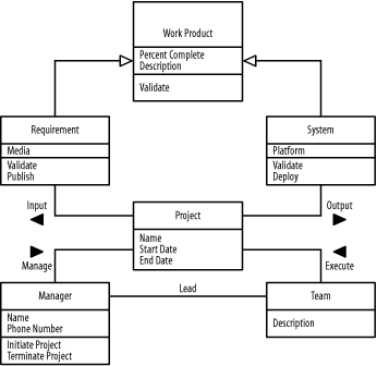 2.4.1.2 Object diagramsObject diagrams depict the structure of a system at a particular point in time. Object diagrams have the following types of elements:
Figure 2-16 is based on the following paragraph from the requirements description provided at the beginning of the chapter:
This paragraph describes a specific situation that the project management system must be able to handle using the various classes that make up the system. We can communicate this information on a single diagram, as shown in Figure 2-16, or by using multiple diagrams, as has been done earlier in this chapter. Chapter 3 describes object diagrams in detail. Figure 2-16. Object diagram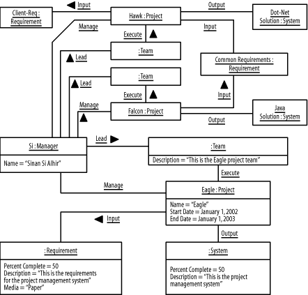 2.4.1.3 Use-case diagramsUse-case diagrams depict the functionality of a system. Use-case diagrams have the following types of elements:
Figure 2-17 is based on the following part of a paragraph from the requirements description provided at the beginning of the chapter:
This identifies specific functionality that the project management system must provide to its users. Chapter 4 describes use-case diagrams in detail. Figure 2-17. Use-case diagram 2.4.1.4 Component diagramsComponent diagrams, also known as implementation diagrams, depict the implementation of a system. Component diagrams have the following types of elements:
Figure 2-18 is based on the following part of a paragraph from the requirements description provided at the beginning of the chapter:
This paragraph describes how the project management system is implemented when it is executing. Chapter 5 describes component diagrams in detail. Figure 2-18. Component diagram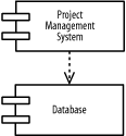 While the object-oriented paradigm focuses on using objects, the component-based paradigm focuses on using components. Both paradigms are based on the principles of abstraction, encapsulation, generalization, and polymorphism. 2.4.1.5 Deployment diagramsDeployment diagrams, also known as implementation diagrams, depict the implementation environment of a system. Note that both component and deployment diagrams are specific types of implementation diagrams. Deployment diagrams have the following types of elements:
Figure 2-19 is based on the following part of a paragraph from the requirements description provided at the beginning of the chapter:
This describes the implementation environment of the project management system. Chapter 5 describes deployment diagrams in detail. Figure 2-19. Deployment diagram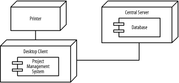 2.4.2 Behavioral ModelingBehavioral modeling assists in understanding and communicating how elements interact and collaborate to provide the functionality of a system. The UML supports a number of diagrams useful for behavioral modeling, and these are briefly described in the following sections. Part III describes these types of diagrams in more detail. 2.4.2.1 Sequence diagramsSequence diagrams, also known as interaction diagrams, depict how elements interact over time. A horizontal axis shows the elements involved in the interaction, and a vertical axis represents time proceeding down the page. Sequence diagrams have the following types of elements:
Figure 2-20 is based on the following part of a paragraph from the requirements description provided at the beginning of the chapter:
This paragraph describes a specific scenario the classes and objects that make up the project management system must be able to handle. Chapter 6 describes sequence diagrams in detail. Figure 2-20. Sequence diagram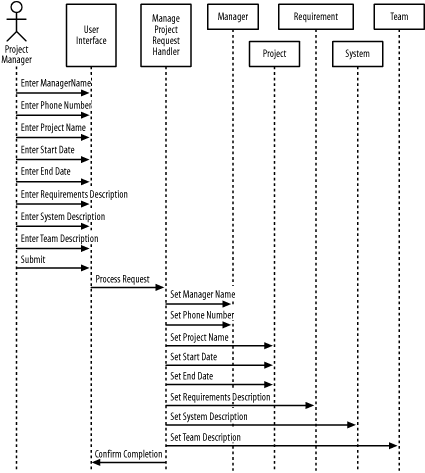 2.4.2.2 Collaboration diagramsCollaboration diagrams, also known as interaction diagrams, depict how elements interact over time and how they are related. Note that both sequence and collaboration diagrams are specific types of interaction diagrams. Collaboration diagrams have the types of elements that are described in the list shown next.
Figure 2-21 is based on the same part from the requirements description provided at the beginning of the chapter as Figure 2-20 but additionally includes the relationships. Chapter 6 describes collaboration diagrams in detail. Figure 2-21. Sequence diagram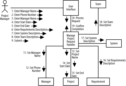 2.4.2.3 State diagramsState diagrams, also known as statechart diagrams, depict the lifecycle of an element. State diagrams have the following types of elements:
Figure 2-22 is based on the following part of a paragraph from the requirements description provided at the beginning of the chapter:
This paragraph describes the lifecycle of a project object that makes up the project management system. Chapter 7 describes state diagrams in detail. Figure 2-22. Sequence diagram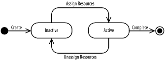 2.4.2.4 Activity diagramsActivity diagrams depict the activities and responsibilities of elements. Activity diagrams have the following types of elements:
Figure 2-23 is based on the same part of the requirements description provided at the beginning of the chapter as Figures Figure 2-20 and Figure 2-21, but emphasizes the activities and responsibilities of a project manager and the project management system. Chapter 8 describes activity diagrams in detail. Figure 2-23. Activity diagram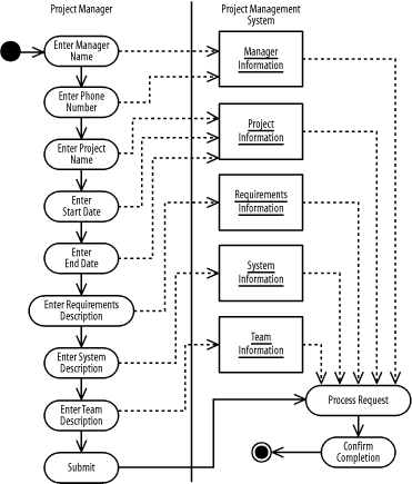 2.4.3 Other ElementsA language often contains elements that are purely notational and other elements that allow for extending the language. UML is no different. UML provides notational items such as notes. Stereotypes and properties allow you to extend the UML. 2.4.3.1 NotesA note, shown as a rectangle with a bent upper-right corner that may be attached to another element using a dashed line, represents a comment similar to comments in programming languages. Figure 2-24 shows a comment attached to the Project class. Figure 2-24. Notes, stereotypes, and properties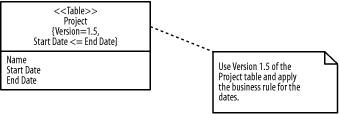 2.4.3.2 StereotypesA stereotype, shown as a text string keyword enclosed in guillemets («», pronounced gee-a-may) or double-angle brackets, before or above the name of an element, represents a specific meaning associated with the element. Figure 2-24 shows a stereotype attached to the Project class in this example, indicating that the class represents a database table. Chapter 9 describes stereotypes in more detail. 2.4.3.3 PropertiesProperties are shown as a comma-delimited list of text strings inside a pair of braces ({}) after or below the name of an element, and expressed in any natural or computer language, represents characteristics of the element. The text string representing a property can take on two forms:
Figure 2-24 shows the properties of the Project class, including the version that is used, as well as the business rule concerning the start and end dates of a project. Chapter 9 describes properties in more detail, and Chapter 10 describes the OCL in more detail. |
|
|
|