|
|
|
3.2 Associations and LinksClass diagrams contain associations, and object diagrams contain links. Both associations and links represent relationships. Associations represent relationships between classes; links represent relationships between objects. The next few sections discuss the UML's representation of associations and links in detail. 3.2.1 AssociationsAs discussed in Chapter 2, an association defines a type of link and is a general relationship between classes. For example, the project management system involves various general relationships, including manage, lead, execute, input, and output between projects, managers, teams, work products, requirements, and systems. Consider, for example, how a project manager leads a team. 3.2.1.1 Binary associationsA binary association relates two classes. For example, one binary relationship in the project management system is between individual workers and their units of work, and another binary relationship is between individual workers and their work products. In a UML class diagram, a binary association is shown as a solid-line path connecting the two related classes. A binary association may be labeled with a name. The name is usually read from left to right and top to bottom; otherwise, it may have a small black solid triangle next to it where the point of the triangle indicates the direction in which to read the name, but the arrow is purely descriptive, and the name of the association should be understood by the classes it relates. Figure 3-9 shows various associations within the project management system using the most basic notation for binary associations. The associations in the figure are as follows:
Notice that a binary association should be named using a verb phrase. Recall from Chapter 2 that you discover associations by focusing on verbs. Figure 3-9. Binary associations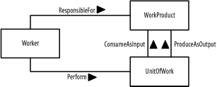 3.2.1.2 N-ary associationsAn n-ary association relates three or more classes. For example, in the project management system, the use of a worker involves the worker, her units of work, and her associated work products. In a UML class diagram, an n-ary association is shown as a large diamond with solid-line paths from the diamond to each class. An n-ary association may be labeled with a name. The name is read in the same manner as for binary associations, described in the previous section. Figure 3-10 shows an n-ary association associated with the project management system using the most basic notation for n-ary associations. This association states that utilization involves workers, units of work, and work products. As with a binary association, an n-ary association is also commonly named using a verb phrase. However, this is not always the case — for example, the n-ary Utilization association shown in Figure 3-10 is described using a noun rather than a verb, because it is named from our perspective rather than the perspective of one of the classes. That is, from our perspective, we want to understand a worker's utilization relative to the other classes. From the worker's perspective, a worker is responsible for work products and performs units of work. Figure 3-10. N-ary association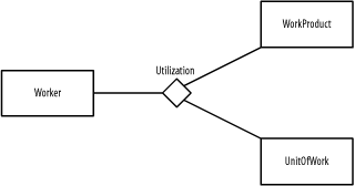 3.2.2 Association ClassesAssociation classes may be applied to both binary and n-ary associations. Similar to how a class defines the characteristics of its objects, including their structural features and behavioral features, an association class may be used to define the characteristics of its links, including their structural features and behavioral features. These types of classes are used when you need to maintain information about the relationship itself. In a UML class diagram, an association class is shown as a class attached by a dashed-line path to its association path in a binary association or to its association diamond in an n-ary association. The name of the association class must match the name of the association. Figure 3-11 shows association classes for the binary associations in Figure 3-9 using the most basic notation for binary association classes. The association classes track the following information:
Figure 3-11. Binary association classes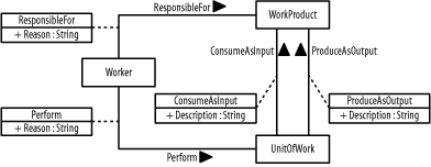 Figure 3-12 shows an association class for the n-ary association in Figure 3-10 using the most basic notation for n-ary association classes. The association class tracks a utilization percentage for workers, their units of work, and their associated work products. Figure 3-12. N-ary association class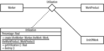 3.2.3 Association EndsAn association end is an endpoint of the line drawn for an association, and it connects the association to a class. An association end may include any of the following items to express more detail about how the class relates to the other class or classes in the association:
3.2.3.1 RolenamesA rolename is optional and indicates the role a class plays relative to the other classes in an association, how the other classes "see" the class or what "face" the class projects to the other classes in the relationship. A rolename is shown near the end of an association attached to a class. For example, a work product is seen as input by a unit of work where the unit of work is seen as a consumer by the work product; a work product is seen as output by a unit of work where the unit of work is seen as a producer by the work product, as shown in Figure 3-13. I will continue to discuss this figure in the next sections. I particularly captured significant detail in one figure so that you can see how much the UMC enables you to communicate in a figure such as this. Figure 3-13. Binary association ends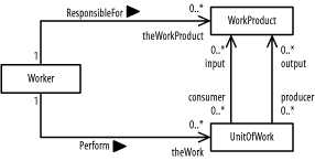 3.2.3.2 NavigationNavigation is optional and indicates whether a class may be referenced from the other classes in an association. Navigation is shown as an arrow attached to an association end pointing toward the class in question. If no arrows are present, associations are assumed to be navigable in all directions, and all classes involved in the association may reference one another. For example, given a worker, you can determine his work products and units of work. Thus, Figure 3-13 shows arrows pointing towards work product and units of work. Given a unit of work, you can determine its input and output work products; but given a work product, you are unable to identify which worker is responsible for it or which units of work reference it as input or output (as shown in Figure 3-13 by the lack of arrows pointing to the Worker class). Figure 3-14 shows navigation arrows applied to an n-ary association. Given a worker, you can reference his work products and units of work to determine his utilization, but given a work product or unit of work, you are unable to determine its utilization by a worker. Figure 3-14. N-ary association ends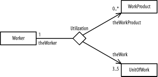 3.2.3.3 MultiplicityMultiplicity (which is optional) indicates how many objects of a class may relate to the other classes in an association. Multiplicity is shown as a comma-separated sequence of the following:
Intervals are shown as a lower-bound .. upper-bound string in which a single asterisk indicates an unlimited range. No asterisks indicate a closed range. For example, 1 means one, 1..5 means one to five, 1, 4 means one or four, 0..* and * mean zero or more (or many), and 0..1 and 0, 1 mean zero or one. There is no default multiplicity for association ends. Multiplicity is simply undefined, unless you specify it. For example:
All this is shown in Figure 3-13. Continuing the example, utilization may be determined for a single worker who must have three to five units of work and zero or more work products, as shown in Figure 3-14. To determine the multiplicity of a class, ask yourself how many objects may relate to a single object of the class. The answer determines the multiplicity on the other end of the association. For example, using Figure 3-13, if you have a single worker object, how many work products can a single worker object be responsible for? The answer is zero or more, and that is the multiplicity shown on the diagram next to the WorkProduct class. Using Figure 3-14, if you have a single worker, to how many work products can the single worker be related to determine the worker's utilization? The answer is zero or more, and that is the multiplicity shown on the diagram next to the WorkProduct class. Another way to determine multiplicity is to ask how many objects of a class may relate to a single object of the class on the other end of an association, or to a single object of each class on the other ends of an n-ary association. The answer determines the multiplicity for the class. For example, using Figure 3-13, how many work products is a single worker responsible for? The answer is zero or more; that is the multiplicity shown on the diagram next to the WorkProduct class. Also, using Figure 3-14, to how many work products is a single worker and a single unit of work related to determine the worker's utilization? The answer is zero or more; that is the multiplicity shown on the diagram next to the WorkProduct class. 3.2.3.4 AggregationAggregation is whole-part relationship between an aggregate, the whole, and its parts. This relationship is often known as a has-a relationship, because the whole has its parts. For example, when you think of workers making up a team, you can say that a team has workers. Aggregation is shown using a hollow diamond attached to the class that represents the whole. This relationship that I've just mentioned between a team and its workers is shown in Figure 3-15. Look for the hollow diamond to the right of the Team class. The filled-in diamonds represent composition, which I'll discuss next. As a UML rule, aggregation is used only with binary associations. Figure 3-15. Aggregation and composition for associations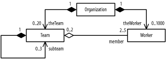 Notice in Figure 3-15 that I've done something different with Team. I've created a circular relationship to allow for subteams. Such a circular relationship is known as a reflexive relationship, because it relates two objects of the same class. 3.2.3.5 CompositionComposition, also known as composite aggregation, is a whole-part relationship between a composite (the whole) and its parts, in which the parts must belong only to one whole and the whole is responsible for creating and destroying its parts when it is created or destroyed. This relationship is often known as a contains-a relationship, because the whole contains its parts. For example, an organization contains teams and workers, and if the organization ceases to exist, its teams and workers also cease to exist. The specific individuals who represent the workers would still exist, but they would no longer be workers of the organization, because the organization would no longer exist. Composition is shown using a filled diamond attached to the class that represents the whole. The relationships between a team, its workers, and an organization are shown in Figure 3-15. The filled-in diamond at the endpoint of the subteam relationship in Figure 3-15 indicates that teams contain their subteams. As a UML rule, composition is used only with binary associations. Notice how much information is being communicated in Figure 3-15. It shows that an organization may contain 0 to 20 teams and 0 to 1,000 workers. Furthermore, each team has 2 to 5 workers and each worker may be a member of 0 to 2 teams. In addition, a team may contain 0 to 3 subteams. To determine if you should use an aggregation or composition, ask yourself a few questions. First, if the classes are related to one another, use an association. Next, if one class is part of the other class, which is the whole, use aggregation; otherwise, use an association. For example, Figure 3-15 shows that workers are part of a team and organization, teams are part of an organization, and subteams are part of teams. Finally, if the part must belong to one whole only, and the whole is responsible for creating and destroying its parts, use composition; otherwise, simply use aggregation. For example, Figure 3-15 shows that a team and worker must belong to one organization only, and the organization is responsible for determining (or creating and destroying) its teams and workers. It also shows that a subteam must belong to one team only, and the team is responsible for determining (or creating and destroying) its subteams. If this is unclear, keep things simple and use associations without aggregation or composition. Composition also may be shown by graphically nesting classes, in which a nested class's multiplicity is shown in its upper-right corner and its rolename is indicated in front of its class name. Separate the rolename from the class name using a colon. Figure 3-16 uses the graphical nesting of teams and workers in organizations to communicate the same information as shown in Figure 3-15. Figure 3-16. Alternate form of composition for associations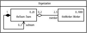 Figure 3-17 uses the graphical nesting of subteams within teams to communicate the same information as Figure 3-15 and Figure 3-16. The result is a nested class inside a nested class. Figure 3-17. Doubly nested composition for associations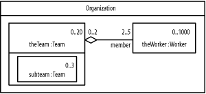 3.2.3.6 QualifiersA qualifier is an attribute of an association class that reduces the multiplicity across an association. For example, Figure 3-13 shows that multiplicity between work products and units of work is zero or more for both associations; that is, there may be many work products associated with a single unit of work and there may be many units of work associated with a single work product. Rather than simply say that there are "many" objects involved in the relationship, you can communicate a more finite number. You can reduce the multiplicity between work products and units of work by asking yourself what you need to know about a unit of work so that you can define a more specific multiplicity — one that isn't unbounded on the high-end. Likewise, you can ask yourself the same question about the association between work product and units of work. If you have a work product and the name of a unit of work, you can determine whether a relationship exists between the two; likewise, if you have a unit of work and the name of a work product, you can determine whether a relationship exists between those two. The trick is to document precisely what information is needed so you can identify the objects on the other end of the relationship. This is where the qualifier comes into play. Essentially, a qualifier is a piece of information used as an index to find the objects on the other end of an association. A qualifier is shown as a small rectangle attached to a class where an object of the class, together with a value for the qualifier, reduces the multiplicity on the other end of the association. Qualifiers have the same notation as attributes, have no initial values, and must be attributes of the association or the class on the other end of the association. The relationships between work products and units of work and their qualifiers are shown in Figure 3-18. The qualifiers indicate that a work product with the name of a unit of work may identify a unit of work, and that a unit of work with the name of a work product may identify a work product. Notice that I've reduced the multiplicity of 0..* shown in Figure 3-13 to 0..1 in Figure 3-18. The qualifier enables me to do this. As a UML rule, qualifiers are used only with binary associations. Figure 3-18. Qualifiers for associations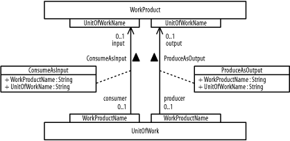 3.2.4 LinksAs discussed in Chapter 2, a link is a specific relationship between objects. For example, the project management system involves various specific relationships, including specific manage, lead, execute, input, output, and other relationships between specific projects, managers, teams, work products, requirements, systems, and so forth. A link is an instance of an association, and the UML supports different types of links that correspond to the different types of associations. The general rules for representing links in a UML diagram are as follows:
The next few sections show how to apply these rules to the various link types. 3.2.4.1 Binary linksA binary link, which is a specific relationship between two objects, is shown as a solid-line path connecting the two objects in a UML object diagram. For example, a specific worker is related to specific units of work and work products in the project management system. A link may have its association name shown near the path (fully underlined), but links do not have instance names. Figure 3-19 shows various objects associated with the classes shown in Figure 3-13 and the association classes shown in Figure 3-11. Additionally, Figure 3-19 includes several link objects. Figure 3-19 describes an anonymous worker that performs a project—a unit of work—that consumes a Problem Statement work product and produces a system work product. ResponsibleFor and Performed are two links in Figure 3-19. Figure 3-19. Binary links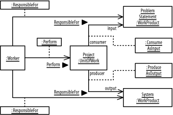 The only difference between a binary link and a binary association is that the binary link is specific, and thus has its association name underlined. 3.2.4.2 N-ary linksAn n-ary link, a relationship between three or more objects, is shown as a large diamond with solid-line paths from the diamond to each object in a UML object diagram. For example, the utilization of a specific worker involves the worker, the worker's specific units of work, and the worker's specific work products in the project management system. A link may have its association name shown near the path, and because a link is specific, its association name should be fully underlined. However, links do not have instance names. As a UML rule, aggregation, composition, and qualifiers may not be used with n-ary links. Figure 3-20 shows various objects associated with the classes shown in Figure 3-14 and the association classes shown in Figure 3-12. Additionally, Figure 3-20 includes a link object named Utilization. Figure 3-20 describes the utilization of an anonymous team, its work, and work products. Figure 3-20. N-ary link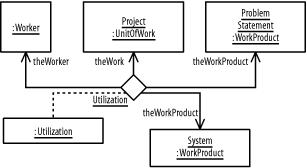 3.2.5 Link ObjectsA link object is a specific instance of an association class, and thus has all the characteristics, including structural and behavioral features, defined by the association class. Structural features include attribute values and perhaps other links. Behavioral features include operations and methods, which are shared by all the links of an association class. Whenever an association has a related association class, each of its links has a corresponding link object. This link object defines attribute values for the link's structural features. In addition, the behavioral features defined by the link's association class apply to the link objects. In a UML object diagram, a link object is shown as an object rectangle attached by a dashed-line path to its link path in a binary link, or attached to its link diamond in an n-ary link. As with all UML elements representing specific objects or links, link object names should be fully underlined. Figure 3-19 shows link objects for the binary associations in Figure 3-13, and Figure 3-20 shows a link object for the n-ary association in Figure 3-14. 3.2.6 Link EndsA link end, similar to an association end, is an endpoint of a link and connects the link to an object. A link end may show its association end's rolename, navigation arrow, aggregation or composition symbol, and values for its association end's qualifiers. 3.2.6.1 RolenamesA link end's rolename must match its association end's rolename. For example, Figure 3-13 shows that a Worker is responsible for a WorkProduct. The specific association used is ResponsibleFor; this same association name is used again in Figure 3-19 to describe the specific links between a specific Worker and the two specific work products: ProblemStatement and System. 3.2.6.2 NavigationLikewise, a link end's navigation must match its association end's navigation. For example, the arrows on the two ResponsibleFor links in Figure 3-19 both point to instances of WorkProduct. This is consistent with Figure 3-13, which shows the arrow for the ResponsibleFor association pointing to the WorkProduct class. 3.2.6.3 MultiplicityMultiplicity is shown only on association ends. This is because an association describes the multiplicity between two or more classes of objects. A link however, is between specific objects. Thus, in an object diagram, multiplicity manifests itself in terms of a specific number of links pointing to a specific number of discrete objects. For example, the multiplicity shown in Figure 3-13 indicates that a Worker object may be responsible for zero to many (0..*) WorkProduct objects. In Figure 3-19, two specific WorkProduct objects are shown. Figure 3-19 is specific, and the specific multiplicity in this case is two: the specific Worker object is responsible for two specific WorkProduct objects. 3.2.6.4 AggregationAggregation is shown using a hollow diamond, as shown in Figure 3-21 through Figure 3-23. Figure 3-21 shows three teams named Eagle, Falcon, and Hawk. Jonathan, Andy, Nora, and Phillip are on the Eagle team, while Nora and Phillip are also on the Hawk team. Figure 3-21. Aggregation and composition for links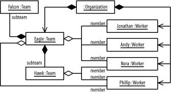 3.2.6.5 CompositionComposition may be shown using a filled diamond or graphical nesting, as in Figure 3-21. Figure 3-21 shows that the two teams, Falcon and Hawk, are subteams of the Eagle team. In addition, the filled-in diamond next to the Organization class indicates that all the individuals on these teams belong to the same organization, and that the Eagle team itself belongs to the organization. Figure 3-22 uses the graphical nesting of teams and workers in organizations to communicate the same information as Figure 3-21. Figure 3-22. Alternate form of composition for links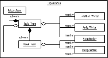 Figure 3-23 uses the graphical nesting of subteams in teams to communicate the same information as Figure 3-21 and Figure 3-22. Figure 3-23. Doubly nested composition for links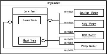 3.2.6.6 QualifiersValues for link qualifiers have the same notation as for object attribute values. Figure 3-24 shows how qualifier values associate a project with its problem statement (named Problem Statement) and system (named PM-System). Figure 3-24. Qualifier values for links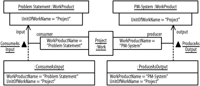 |
|
|
|