

|
|
1.3 System ResourcesPCs have four types of system resources—Interrupt Request lines, DMA channels, I/O ports, and memory ranges. Many system components and peripherals require one or more of these resources, which raises the twin problems of resource availability and resource conflicts. Resource availability is particularly important with regard to IRQs, which are in high demand, and of which only 16 exist. Resource conflicts can occur when two devices are assigned the same resource, in which case one or both devices may not function or may function unpredictably. Resource conflicts may occur even with plentiful resources, such as I/O ports, where many are available and only a few are in use. A frequent cause of problems when building or upgrading PCs is a shortage of required resources or unintentional resource conflicts that occur when a new component is installed that was inadvertently configured to use a resource already in use. Two technologies, PCI and Plug-N-Play, used in conjunction with recent versions of Microsoft operating systems (Windows 95 OSR2, Windows 98, and Windows 2000/XP) go a long way toward extending the availability of resources and preventing conflicts. Even in such an ideal environment, however, resource conflicts sometimes occur, particularly if you are using older "legacy" hardware. The following sections describe what you need to know about PC resources and how to manage them. 1.3.1 Interrupt Request Line (IRQ)When a component or peripheral, such as a network adapter or sound card, needs to get the CPU's attention, it does so by generating a signal on an Interrupt ReQuest Line (IRQ). Table 1-2 lists IRQs and the devices that typically use them.
An 8-bit ISA slot contains physical IRQ lines only for IRQ 02 through IRQ 07, because IRQ 00 and IRQ 01 are reserved for system functions. A 16-bit ISA slot contains physical IRQ lines for IRQs 03 through 07, 09 through 12, 14, and 15. IRQ 09 is mapped to IRQ 02, allowing 8-bit ISA cards to recognize IRQ 09 as IRQ 02. IRQs 00, 01, 02, 08, and 13 are not present in any slot, and so cannot be assigned to devices. If the processor receives two or more interrupts simultaneously, it processes them in order of priority. On 8-bit systems (PCs and XTs), the lower-numbered IRQ always takes priority. That is, IRQ 00 is the highest priority, and IRQ 07 is the lowest. 286 and higher systems use a second PIC to add a second set of eight IRQs, cascaded from IRQ 02. That changes IRQ priority from the simple numerical order used by 8-bit systems. On 16-bit and higher systems, IRQ 00 is still the highest priority, followed by IRQ 01 and 02. But because IRQ 02 is the cascade IRQ, the IRQs that it supports—IRQ 08 through IRQ 15—are next in priority. IRQ 03 follows IRQ 15 in priority, and then in numerical order through IRQ 07, the lowest priority. Whenever possible, assign "important" devices to higher-priority IRQs. For example, if you have a serial mouse and a modem, assign the modem to COM2: (IRQ3) and the mouse to COM1: (IRQ4). Because the modem is on the higher-priority IRQ, it is serviced first if the modem and the mouse generate interrupts simultaneously.
1.3.1.1 ISA Interrupts Versus PCI InterruptsISA and PCI handle interrupts very differently. ISA expansion cards are configured manually for IRQ, usually by setting a jumper, but sometimes by running a setup program. All ISA slots have all IRQ lines present, so it doesn't matter which card is placed in which slot. ISA cards use edge-sensitive interrupts, which means that an ISA device asserts a voltage on one of the interrupt lines to generate an interrupt. That in turn means that ISA devices cannot share interrupts, because when the processor senses voltage on a particular interrupt line it has no way to determine which of multiple devices might be asserting that interrupt. For ISA slots and devices, the rule is simple: two devices cannot share an IRQ if there is any possibility that those two devices may be used simultaneously. In practice, this means that you cannot assign the same IRQ to more than one ISA device. PCI cards use level-sensitive interrupts, which means that different PCI devices can assert different voltages on the same physical interrupt line, allowing the processor to determine which device generated the interrupt. PCI cards and slots manage interrupts internally. A PCI bus normally supports a maximum of four PCI slots, numbered 1 through 4. Each PCI slot can access four interrupts, labeled INT#1 through INT#4 (or INT#A through INT#D). Ordinarily, INT#1/A is used by PCI Slot 1, INT#2/B by Slot 2, and so on.
Bridging circuitry within the chipset allows additional PCI or other buses to be cascaded from the primary PCI bus. For example, the PCI-to-ISA bridge present in most current chipsets allows cascading an ISA bus from the primary PCI bus. One function of the bridging circuitry is to convert PCI interrupts to ISA interrupts when a PCI device needs to get the processor's attention. PCI interrupts do not correspond directly to ISA IRQs, although an INT# can be mapped to an IRQ via the PC's interrupt handler if the card using that INT# requires an IRQ. Some configuration firmware restricts mapping PCI interrupts to IRQ 09, 10, or 11 or Auto, while others allow mapping any INT# to any available IRQ. In general, leave INT-IRQ mapping for all PCI slots set to Auto unless you have good reason to assign a specific IRQ. Sometimes a card with a dynamically mapped IRQ may work fine with some programs and not others. For example, many older games expect to find a sound card at IRQ 05. If you have a PCI/PnP sound card installed in PCI Slot 3, you can use INT-IRQ mapping to assign IRQ 05 to that slot and card, keeping the old games happy. PCI expansion cards are normally assigned an IRQ dynamically, either by the BIOS or by Windows, depending on the version of Windows being used and the PCI/PnP configuration options in effect. On bridged PCI-ISA systems, ISA IRQs 00, 01, 02, 08, and 13 are reserved for critical system functions. IRQs 03 through 07, 09 through 12, 14, and 15 can each be programmed using the CMOS Setup PCI/PnP configuration utility as being owned by either the PCI bus or the ISA bus, but not both. The terminology for this varies. Some utilities allow you to specify each IRQ as PCI/ISA PnP or Legacy ISA (or similar words). Others allow you to specify each IRQ as Level-Sensitive or Edge-Sensitive (or similar words). In either case, the effect is the same. If you are installing a "legacy" card (i.e., a non-PnP ISA card), you can use static IRQ mappings to assign a specific IRQ to that card. For example, if you install an old ISA sound card that requires IRQ 05, use the PCI/PnP configuration utility to set IRQ 05 for Legacy ISA or Edge-Sensitive, thereby reserving that IRQ for that card. 1.3.1.2 PCI Bus IRQ SteeringPCI Bus IRQ Steering is a function built into Windows 95 OSR2 or higher and Windows 98 (but not NT4 or Windows 2000). IRQ Steering allows Windows itself to assign IRQs to PCI devices. With earlier versions of Windows 95, the BIOS assigns IRQs to PCI devices, and Windows must accept the decisions made by the BIOS IRQ Steering. If Windows IRQ Steering is enabled, Windows can override those BIOS decisions, although it seldom does so. OSR2 disables IRQ Steering by default; Windows 98 enables it by default. Windows IRQ Steering allows Windows to reassign PCI interrupts automatically to accommodate the inflexible requirements of ISA devices. For example, assume a PC with a BIOS that does not recognize non-PnP ISA cards (that is, IRQ Steering is not implemented in BIOS) is running Windows 98 with IRQ Steering disabled. The PC is properly configured with all PCI devices, and the BIOS has assigned IRQ 11 to a Creative SoundBlaster AudioPCI 128 sound card. You then open the case and install a 3Com 3C509 network adapter (a non-PnP ISA card), which is also configured for IRQ 11. When you restart the system, a conflict exists between the sound card on IRQ 11 and the network card that is also on IRQ 11. If you enable Windows 98 IRQ Steering and restart the system, IRQ Steering takes the following actions during boot:
When the system restarts, the sound card is now assigned to IRQ 10, the network card is still IRQ 11, and both devices work. Note that IRQ Steering does nothing that you cannot do for yourself. It simply automates the process of resolving IRQ conflicts when ISA devices are present in a PCI system. To view the IRQ assignments made by IRQ Steering, right-click the My Computer icon, choose Properties, click the Device Manager tab, and double-click the Computer icon at the top of the tree to display the View Resources page of the Computer Properties dialog, shown in Figure 1-3. IRQs that IRQ Steering has assigned to PCI are flagged with an entry labeled IRQ Holder for PCI Steering. This flag does not indicate that another device is assigned to the IRQ, but simply that IRQ Steering has reserved that IRQ for PCI, making it unavailable to ISA devices even if no PCI devices are currently using that IRQ. Figure 1-3. The View Resources page of the Computer Properties dialog displays global resource allocations for IRQ, DMA, I/O ports, and memory ranges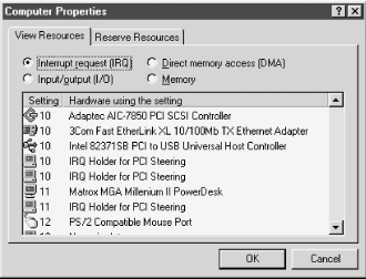 IRQs that both the BIOS and Windows 98 have assigned to PCI are flagged twice. In Figure 1-3 IRQ Steering has assigned IRQ 10 as a PCI interrupt, which is being shared by a SCSI host adapter, a network adapter, and the USB host controller. Both BIOS IRQ Steering and Windows 98 IRQ Steering have assigned IRQ 10 to PCI. The Matrox video card on IRQ 11 is the only device assigned to that IRQ, and only BIOS IRQ Steering has assigned an IRQ Holder. To view or change settings for IRQ Bus Steering itself, right-click the My Computer icon, choose Properties, and click the Device Manager tab. Double-click System Devices to expand the tree, and then double-click PCI Bus to display the PCI Bus Properties dialog. Click the IRQ Steering tab to display the IRQ Steering page of the PCI Bus Properties dialog, shown in Figure 1-4. Figure 1-4. The IRQ Steering page of the PCI bus Properties dialog allows you to enable or disable Windows 98 IRQ Steering, configure it, and view its current status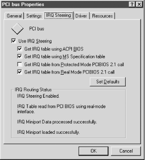 The IRQ Routing Status pane at the bottom of the dialog displays the current status of IRQ Steering. Windows 98 enables IRQ Steering using the defaults shown. Leaving this checkbox marked means that Windows 98 manages IRQ Steering. To disable Windows 98 IRQ Steering and allow the BIOS to manage IRQ Steering, clear the Use IRQ Steering checkbox and restart the PC. If you do that, the Windows Find New Hardware Wizard runs after the restart, locates the "new" devices, and installs drivers for them. The Get IRQ table... checkboxes are a ranked priority list of the methods Windows can use to obtain the data it needs to manage IRQ Steering. Clearing one of these checkboxes causes Windows not to attempt that method. In Figure 1-4, Windows first attempts to obtain this data using the ACPI BIOS. That fails, so it next attempts to get the data using the MS Specification Table, which also fails. The Protected Mode PCIBIOS 2.1 method is not checked, so Windows does not attempt to use that method. Finally, Windows attempts to get the data using a Real Mode PCIBIOS 2.1 call, which succeeds. In general, leave IRQ Steering enabled. If problems occur with a PCI device being recognized or configured properly, take the following steps in order until the problem is resolved:
1.3.2 Direct Memory Access (DMA)Direct Memory Access (DMA) is a means by which devices can exchange data with memory or with each other without requiring intervention by the processor. Standard DMA allows a device to exchange data with memory, but not with another device. Bus Mastering DMA allows two devices to communicate directly with each other. The advantage of using DMA is that it reduces the load on the processor, allowing it to perform other tasks. There are even fewer DMA channels than IRQs—eight versus sixteen—but DMA channels are much less in demand than IRQs, so DMA channel availability is almost never an issue on ISA systems. Table 1-3 lists DMA channels and their typical uses.
DMA 2 is used by nearly all systems for the floppy disk drive controller. Except for DMA 4, which is a dedicated cascade channel, the other DMA channels are available for use with expansion cards. DMA 0 is almost never used because, although it appears only in 16-bit slots, it supports only 8-bit transfers. Most ISA sound cards require two DMA channels, with 8-bit sound using DMA 1 and 16-bit sound using DMA 5. Note that these DMA channels pertain only to ISA cards. PCI devices do not require one of these DMA channels to use DMA. For example, if you enable DMA transfer mode on one or both of the embedded PCI IDE controllers, you will find that they operate in DMA mode without occupying ISA DMA channels.
1.3.3 I/O PortsInput/Output ports (I/O ports) are ranges of addresses that function like mailboxes, allowing programs and components to exchange messages and data. An I/O port has a base address, which is the hexadecimal address of the first byte allocated to that I/O port, and a length, which is also expressed in hexadecimal. For example, many network adapters default to base address 300h and are 20h bytes (32 decimal bytes) long, and so occupy the range 300-31Fh. There's no shortage of I/O ports, because thousands exist. We have never seen I/O port conflicts with PCI devices operating in a PnP environment, but I/O port conflicts commonly occur when two ISA devices are unintentionally assigned overlapping ranges. For example, another common base address for network adapters is 360h (range 360-37Fh). Unfortunately, that range overlaps the range of LPT1: (base address 378h), so setting a network card to 360h results in conflicts with the parallel port. 1.3.4 Memory RangesThe original IBM PC used an 8088 processor, which supported up to 1 MB of physical memory, addressed as sixteen 64 KB segments. Memory locations are enumerated in hexadecimal, so the first segment includes the addresses 00000h through 0FFFFh (0 through 65,535 decimal) and the sixteenth includes the addresses F0000h through FFFFFh (983,040 through 1,048,575 decimal). The first ten of those segments—00000h through 9FFFFh—comprise the base 640 KB of memory addresses that are accessible by the operating system and programs. The last six segments—A0000h through FFFFF—comprise the 384 KB of upper memory addresses (the Upper Memory Area or UMA) reserved for system use. The first two UMA segments (A0000h through BFFFFh) are reserved for video memory. The second two UMA segments (C0000h through DFFFFh) are reserved address space for ROM BIOSes that reside on some adapters, such as video cards, SCSI host adapters, and network adapters. The final two UMA segments (E0000h through FFFFF) are reserved for the motherboard BIOS. Modern processors use a flat (unsegmented) 32-bit address space, which allows them to access up to 4 GB (4,096 MB, or 4,294,967,296 bytes) of distinct memory addresses. That additional address space means that memory addresses are expressed as eight rather than five hexadecimal characters (e.g., addresses for the first MB are expressed as 00000000h through 000FFFFFh). Because few systems have anywhere near 4 GB of physical memory installed, huge ranges of unused memory addresses are available for assignment to devices that require memory ranges. Which of those ranges are used depends on how much physical memory is installed and which operating system you run. Windows NT 4 uses address ranges from the UMA of the first megabyte (000A0000h through 000FFFFFh) for the original purposes of addressing video memory, adapter ROMs, and so on. It uses address ranges at the top of its address space, F0000000h and above (up near 4 GB), to provide additional memory ranges for which there is inadequate room in UMA. Windows 98 does the same, but also uses memory ranges immediately above the end of the range occupied by physical RAM. Memory range conflicts are seldom a problem on modern computers running recent versions of Windows. 1.3.5 Viewing and Reserving System ResourcesWindows 9X and Windows NT both provide convenient means to view the resources that are in use. Windows 98 also allows you to reserve resources manually for non-PnP ISA devices on systems with a BIOS that does not support IRQ Steering. 1.3.5.1 Viewing Resources with Windows 2000 or Windows XPTo view system resources with Windows 2000 or Windows XP (in Classic Mode), right-click My Computer, choose Properties, display the Hardware tab, and then click the Device Manager button to display the dialog shown in Figure 1-5, which lists all installed devices. Clicking the + icon (or double-clicking a branch name) expands the list to show individual devices within that branch. If a problem exists with a device (a resource conflict, missing driver, etc.), Windows 2000/XP automatically expands the branch that contains that device and flags the device with an alert icon. Figure 1-5. Windows XP Device Manager displays all installed devices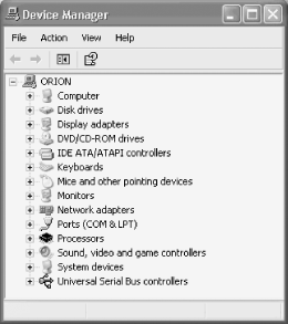 To view a global list of resources, click the View menu and select the Resources by Type option to display the Device Manager window shown in Figure 1-6. Expand the listing for the type of resource you want to view. Figure 1-6 shows that ISA IRQs 2, 5, 6, 7, 10, and 11 are available for use by new devices. Figure 1-6. Windows XP Device Manager displays used and available IRQs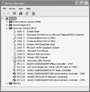 To view all resources being used by a particular device, expand the Device Manager tree (see Figure 1-5), double-click the device name to display the Properties sheet for that device, and display the Resources tab. Figure 1-7 shows the Properties sheet for an ATI RAGE 128 Pro AGP video card. The Resource type pane displays all resources assigned to that device, although you may have to scroll the list to see all items. If a resource conflict exists, Windows 2000/XP displays a list of other devices using the same resource(s) in the Conflicting device list pane. Figure 1-7. The Properties sheet for a device lists all resources allocated to that device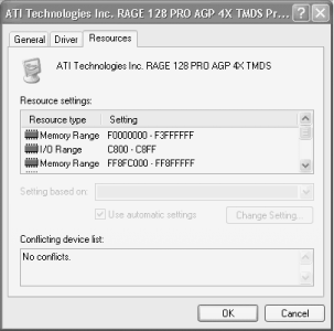 1.3.5.2 Viewing Resources with Windows 9XTo view system resources with Windows 98, right-click My Computer, choose Properties, and click the Device Manager tab to display the System Properties dialog shown in Figure 1-8, which lists all installed devices. Clicking the + icon (or double-clicking a branch name) expands the list to show individual devices within that branch. If a problem exists with a device (a resource conflict, missing driver, etc.), Windows 98 automatically expands the branch that contains that device and flags the device with an alert icon. Figure 1-8. Windows 98 Device Manager displays all installed devices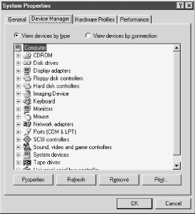 To view a global list of resources, double-click the Computer branch to display the View Resources page of Computer Properties, shown in Figure 1-9. Choosing any of the four option buttons immediately displays a global list of assignments for that resource, allowing you to determine easily which resources are unassigned. Figure 1-9 shows that IRQ 03, normally assigned to Communications Port (COM2), is available for use by a new device. Figure 1-9. The View Resources page of Computer Properties lists resources in use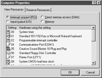 To view all resources being used by a particular device, expand the Device Manager tree (see Figure 1-8) and double-click the device name to display the Properties sheet for that device. Figure 1-10 shows the Properties sheet for a Matrox Millennium II video card. The Resource type pane displays all resources assigned to that device. If a resource conflict exists, Windows 98 displays a list of other devices using the same resource(s) in the Conflicting device list pane. Figure 1-10. The Properties sheet for a device lists all resources allocated to that device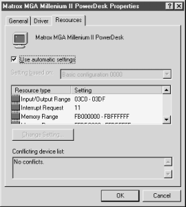 1.3.5.3 Reserving Resources with Windows 9XIf the system BIOS is up-to-date and all expansion cards are PnP-compliant, Windows 98 and PnP normally configure the system properly without further ado. However, if the system has an older BIOS and/or you need to install one or more cards that are not PnP-compliant, conflicts may occur because the BIOS and Windows cannot determine which resources those older cards need. For such situations, Windows allows you to specify manually which resources these older cards require, removing them from the pool of resources that Windows manages automatically. To reserve resources, first examine the documentation and settings for the card to determine which resources (IRQ, DMA, I/O ports, and memory ranges) it requires. Display Device Manager and click the Reserve Resources tab to display the dialog shown in Figure 1-11. This dialog lists any resource reservations already in effect, and allows you to modify existing reservations and add new reservations. Mark one of the four option buttons to select the type of resource for which you want to add a reservation or view existing reservations. Figure 1-11. The Reserve Resources dialog allows you to remove resources from the pool available to Windows and assign those resources manually to legacy devices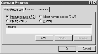 To add a resource reservation, click Add to display the Edit Resource Setting dialog, whose appearance varies depending on the type of resource you are adding a reservation for. Figure 1-12 shows the dialog for reserving an IRQ. Use the up and down arrows to specify a value for the resource to be reserved and click OK. You can reserve multiple resources in a single session by repeatedly selecting resource type and adding reservations. When you finish reserving resources, click OK to store the resource reservations and then restart the system to put the changes into effect. Figure 1-12. The Edit Resource Setting dialog allows you to specify the resource to be reserved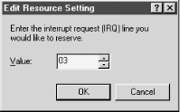 Device Manager initially displays reserved resources as System Reserved, as shown in Figure 1-13. However, once you restart the computer, that resource will no longer be displayed in Device Manager. Figure 1-13. Device Manager lists reserved resources as System Reserved, as for IRQ 03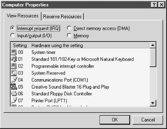
1.3.5.4 Viewing Resources with Windows NT 4Windows NT 4 has neither Device Manager nor PnP support beyond the minimum ability to recognize PCI PnP devices. Despite that, we actually experience fewer resource conflicts with PCI devices on Windows NT systems than on Windows 95/98 systems. With the sole exception of installing ISA PnP cards, such as a SoundBlaster, Windows NT usually just works. However, if you are installing a legacy ISA card on a Windows NT system, you need to configure it to use resources that are not already in use. To view existing resource allocations, choose Start
Figure 1-14. The Windows NT Diagnostics Resources page displays a global list of assigned resources of the type selected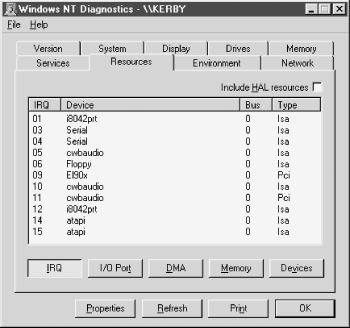 Click the Devices button to display a list of installed devices, shown in Figure 1-15. Figure 1-15. The Resources page Devices view shows a list of all installed devices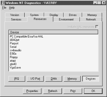 To view all resources allocated to a particular device, double-click that device to display the <device-name> Properties dialog, shown in Figure 1-16. Figure 1-16. The <device-name> Properties dialog lists all resources used by the device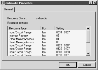
|

|
|