
|
|
26.3 Power ConnectorsAll power supplies provide two types of power connectors. The first powers the motherboard and differs according to form factor. The second powers drives and other internal peripherals, and comes in two varieties, which are described below. Tower/AT and Tower/BAT power supplies include a third type of power connector—a high-voltage cable that connects the power supply to an external main power switch. 26.3.1 AT Main Power ConnectorTable 26-6 lists the standard AT Main Power Connector pinouts used by all AT power supply variants, including Desktop/AT, Tower/AT, Desktop/BAT, Tower/BAT, and LPX. PC/XT power supplies use the same pinouts, except that pin P8-2 is unused. In addition to supplying various standard voltages, this connector includes a special-purpose pin. Pin P8-1, PG, carries the Power Good signal, which the power supply asserts once it has started and stabilized. The motherboard will not attempt to boot until the power supply asserts PG.
Note that P8 and P9 are separate connectors from the power supply, but mate to a combined connector on the motherboard.
P8 and P9 were IBM's original designation for these connectors. Not all power supplies or motherboards label these connectors, so you may have to determine which is P8 and which is P9 by examining wire colors. The colors shown are those most commonly used, but some AT power supplies use the alternative (ATX) color coding shown in parentheses. We have also seen AT power supplies that use completely nonstandard wire colors, such as green for ground wires. When installing an AT power supply, the key factor is to ensure that, regardless of wire colors or connector labels, the connectors are aligned so as to place all four ground pins contiguously. It's safer still to examine the documents for the motherboard and power supply. We have seen a few proprietary motherboards and power supplies that used standard connectors but with completely nonstandard pinouts. This was clearly done to force customers to purchase replacement components from the original vendor, and is happily not something you're likely to encounter on any recent system. 26.3.2 ATX Main Power Supply ConnectorTable 26-7 lists the pinouts for the ATX Main Power Supply Connector of an ATX power supply. This is a 2 x 10 connector with pin 1 keyed. The motherboard connector is a Molex 39-29-9202 or equivalent. The power supply connector is a Molex 39-01-2200 or equivalent. All wires are 18 AWG, except pin 11, which is specified as 22 AWG. For power supplies 300W or larger, the specification recommends using 16 AWG wires for +3.3VDC, +5VDC, and COM (ground). Note that wire colors are those recommended and commonly used, but may vary.
In addition to supplying various standard voltages, this connector includes four special-purpose pins:
26.3.3 ATX Auxiliary Power Supply ConnectorThe ATX Auxiliary Power Supply Connector, shown in Table 26-8, is recommended by the ATX Specification Version 2.03 for motherboards that require 250W or 300W power supplies. This is an in-line 6-pin connector with pin 6 keyed. The motherboard connector is a Molex in-line 6-pin 15-48-0412 header or equivalent. The power supply connector is a Molex 90331-0010 or equivalent. Few inexpensive power supplies provide this connector, but it is present on many better power supplies. Few motherboards include this connector. Wire colors are standard.
26.3.4 ATX Optional Power Supply ConnectorIn addition to the main and auxiliary power connectors, ATX 2.03 defines the ATX Optional Power Supply Connector, shown in Table 26-9. This is a 2 x 3 connector with pin 1 keyed. The motherboard connector is a Molex 39-30-1060 or equivalent. The power supply connector is a Molex 39-01-2060 or equivalent. All wires are 22 AWG. Wire colors are standard; the first color indicates the base color, and the second the stripe color.
ATX Optional Power Supply Connector signals perform the following functions:
26.3.5 ATX12V Power Supply ConnectorWith the introduction of the Pentium 4 processor, Intel extended the ATX 2.03 specification to define a new type of power supply called ATX12V, which is a superset of ATX 2.03. ATX12V power supplies include an additional 2 x 2 4-pin +12V power connector, shown in Table 26-10. The purpose of this new connector is to deliver more +12V current to the motherboard than is available from the standard ATX main power connector. The presence of the 4-pin +12V connector indicates that a power supply is ATX12V. The absence of that connector indicates that it is a standard ATX power supply. Wire colors are standard.
According to Intel's policy, all Pentium 4 motherboards and all power supplies used with those motherboards must include the 4-pin +12V connector. Because installing such motherboards in existing systems may also require upgrading the power supply, some third-party motherboard makers have produced motherboards that lack the 4-pin +12V connector. This allows those motherboards to be installed in existing systems without a power supply upgrade, but we regard this as poor practice and suggest you avoid using such motherboards. In addition to the new 4-pin +12V connector, ATX12V power supplies must also provide higher +5VDC standby voltage, required for systems that meet Intel's Instantly Available PC initiative.
Figure 26-1. Pentium 4 12VATX Adapter The requirement for the new connector is due both to increased current draw by Pentium 4 processors and a shift in Intel's plans for future motherboards. Current ATX 2.03 motherboards power components with DC/DC conversion from +5VDC and +3.3VDC sources. However, relative to +12VDC DC/DC conversion, +5VDC and +3.3VDC DC/DC conversion yields lower power transmission and conversion efficiencies. The change in emphasis to +12VDC DC/DC conversion provides increased efficiency and flexibility for forthcoming motherboards. 26.3.6 NLX Power ConnectorsThe NLX Main Power Supply Connector uses the same pinouts, wire colors, and physical connectors as the ATX Main Power Supply Connector shown in Table 26-7. The NLX specification also defines the NLX Optional Power Supply Connector, shown in Table 26-11. This connector uses the same physical connectors and 22 AWG wire as the ATX Optional Power Supply Connector described in the preceding section, but uses different wire colors and a slightly different pinout. Wire colors are standard.
Pin 5 (1394) on this connector is analogous to pin 5 (1394V) on the ATX connector, and also supplies voltage to unpowered 1394 devices. However, rather than using pin 4 as a ground return path for 1394 voltage, this connector leaves pin 4 unconnected. It appears unwise to share the main system ground return path with the ground return path for unregulated 1394 voltage from pin 5, particularly with pin 4 sitting there so obviously unused. If you understand the reason for this difference, please let us know. 26.3.7 SFX Power ConnectorsThe SFX Baseboard Connector uses the same pinouts, wire colors, and physical connectors as the ATX Main Power Supply Connector shown in Table 26-7, with one or two exceptions:
The SFX specification also defines the required SFX Control Connector, shown in Table 26-12. This connector uses the same physical connectors and 22 AWG wire as the ATX and NLX Optional Power Supply Connectors described in the preceding sections, but has only one connection, FanON/OFF, which corresponds to FanC. Wire color is standard.
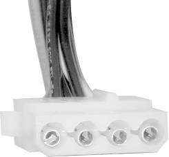
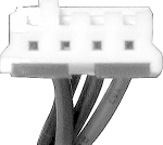
26.3.8 Power-Supply-to-Device ConnectorsPower supplies provide two types of connectors to power disk drives and other internal peripherals:
Figure 26-2. Peripheral Connector
Figure 26-3. Floppy Drive Connector
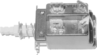
The number and type of device connectors provided are loosely linked to the form factor and power rating of the power supply. Generally, power supplies with low power ratings and those designed for smaller cases provide fewer device connectors, sometimes as few as three. Power supplies with higher power ratings and those intended to fit large tower cases provide more device connectors, sometimes as many as a dozen. So long as you do not exceed the power supply capacity, you can freely clone device connectors by adding Y-splitters, which are available for a couple dollars at any computer store. 26.3.9 Main Power Switch Power ConnectorsDesktop/AT and Desktop/BAT power supplies have a built-in paddle switch to turn power on and off. ATX and ATX-variant power supplies seldom have a physical power switch, because they are turned on and off by the motherboard. Some ATX power supplies have a rocker switch on the back of the power supply that disconnects the power supply entirely from mains power. This can be useful because the alternative is disconnecting the power cable when you need to kill all power to the system, including +5VSB, which is ordinarily always present. Tower/AT and Tower/BAT power supplies have no built-in main power switch. Instead, they have four power leads that connect to a push-button or toggle switch on the case, as shown in Figure 26-4. These leads, which are usually white, black, blue, and brown, carry AC mains voltage to the power supply. Figure 26-4. Typical connections for a Tower/AT or Tower/BAT power switch
26.3.10 Real-World Power Supplies ComparedTable 26-13 lists the output by voltage of three nominally 300-watt power supplies. The PC Power & Cooling Turbo Cool 300 ATX is a premium unit, with a street price of about $90; the Antec PP303X is a name-brand unit that sells for about $40; the Astec SA302-3515-288 is not readily available to individuals, but is shown for comparison because many first-tier OEMs (such as Compaq, Dell, Gateway, and IBM) use Astec power supplies for at least some of their systems. We would like also to have compared a no-name Pacific Rim power supply, but finding technical specifications for such units is impossible, probably because they vary so much from one lot to another that no one bothers to test them. The three key voltage rails are +3.3V (used to power processors and memory), +5V (used to power other electronic components and some drive motors), and +12V (used to power most disk drive motors). Note that, although all the power supplies list individual maximum outputs for +3.3V and +5V, they also note maximum combined output of +3.3V and +5V-150W for the PC Power & Cooling unit, 160W for the Antec, and 170W for the Astec unit.
The main differences between these power supplies are as follows:
A more subtle aspect of nominal wattage is component loading. A premium power supply may deliver its rated wattage while driving its components at only 50% of their rated capacity; a midrange name-brand power supply may deliver near its rated wattage while driving its components at 70% of their rated capacity. A no-name power supply will likely deliver nowhere near its rated wattage, and will drive its components at 100% (or even more) of their rated capacity to do so. Component loading has two important aspects. First, components driven at a fraction of their rated capacity are likely to exceed their design life significantly, while those driven at (or above) their designed limits are likely to be short-lived. Second, a component that is "loafing" is likely to perform much better than one that is being driven at or above its design capacity. For example, components designed to supply +3.3V and driven at 50% of capacity are likely to supply 3.3V bang-on; those driven at 100% of capacity may deliver 3.3V nominal, but the actual voltage may vary significantly. Unfortunately, short of disassembling the power supply (never a good idea) and checking the number, size, and quality of the components, about the only thing you can do to assure that the power supply you choose uses good components is to buy a good name-brand power supply. Comparing the full spec sheets for these three power supplies turns up other differences not shown in the table, of varying significance. For example, the PC Power & Cooling unit provides both the standard 20-pin ATX Main Power Supply Connector and the recommended 6-pin ATX Auxiliary Power Supply Connector, while the Antec and Astec units provide only the standard 20-pin connector. The hold time of the PC Power & Cooling unit is 20 ms, which is the minimum required for ATX compliance. The hold time of the Antec is specified as "< 20 ms" and that of the Astec as 17 ms at 115VAC input, which means that technically neither of these units is ATX compliant. In short, there are very real differences between power supplies, even if they have the same nominal rating. The PC Power & Cooling unit is a superb power supply, which will supply clean, closely regulated power even when driven at its rated wattage, and is unlikely to fail even if used 24 x 7 at its rated output power. The Antec unit is a very good power supply, likely to work reliably in less demanding applications. The Astec unit is robust, but relatively poorly regulated, particularly relative to the PC Power & Cooling unit. About the best you can say for no-name units is that power is likely to come out of them, although how much, how well-regulated, and for how long is in doubt. |

|
|