28.1 Step 1: Prepare the Case
If you are recycling an old case, first remove all components
and clean the case thoroughly, using a soft brush and vacuum cleaner
to remove dust and a cleaner like Fantastic or Formula 409 to remove
grime. We sometimes take really filthy cases outside and literally
hose them down (after first removing the power supply). If you do
that, use a hair dryer to make sure the case is dry before you begin
installing components. If you're not in a hurry,
it's better still to let it sit a week or two and
dry naturally. If the power
supply has been in use for some time, it will likely have accumulated
a lot of dust inside it. Do your best to remove dust using a brush
and compressed air (the air hose at the gas station works well), but
do not remove the cover from the power supply. Whether the case is
new or old, check it thoroughly for sharp edges and burrs and file
down any you find. That saves a lot of bloodshed later. Once the case
is clean, dry, and defanged, proceed as follows:
Verify that all components are present, including the power cord and
the package of small mounting hardware and other incidentals. If the
case uses drive rails, there should be sufficient rails to mount a
drive in each bay.
Remove the cover(s) and set them aside. If it is not obvious how to
do so, see the manufacturer's instructions. You want
the case wide open while you work on it. If the front bezel is
removable, you may or may not need to remove it to mount drives. Most
removable front bezels simply snap on and off bottom-first, but some
are secured with screws. Some cases have a removable motherboard
tray. If so, remove it also. (See Figure 28-1.)
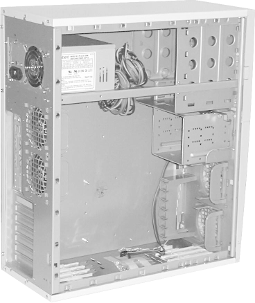 Remove all drive bezels from the front of the case
to give you easy access later when you're installing
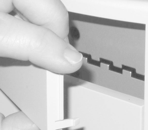
drives. Depending on case design, you may have to remove the front
case bezel before you can remove drive bezels. Most cases use plastic
drive bay bezels, which snap into place using a small hook on each
side to secure them to the chassis. To remove these bezels, use a
small flat-blade screwdriver to bow them slightly until the hooks are
clear and then pull them out. Some cases use metal drive bay bezels,
which are secured with a screw on each side. (See Figure 28-2.)
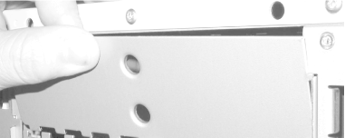
Most cases have metal plates at the front of each drive bay,
immediately behind the bezel, to shield against RFI. On some cases,
these plates are discrete pieces, mounted with screws or spring-clip
retainers. On inexpensive cases, the plates are often stamped as a
part of the chassis and may have to be twisted out with pliers or a
screwdriver. Doing that may leave a sharp barb. File it down now or
it will cut you later. Cases often arrive with the plates already
removed from one floppy drive bay and one externally accessible 5.25"
drive bay (for a CD or DVD drive). You need not remove the metal
plates from positions where you will not be mounting externally
accessible drives. To make the system easier to work on, we sometimes
remove all anti-RFI plates, risking the wrath of the
FCC. (See Figure 28-3.)
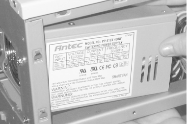
 If you order a case and power supply together, the case usually
arrives with the power supply installed. If so, verify that all
screws securing the power supply to the case are tight and that the
voltage selector (if present) is set to the proper input voltage. If
you order a power
supply separately, install it by aligning any locking tabs and slots,
sliding the power supply into position, and securing the screws.
Manufacturers often use cable ties to secure the wires coming from
the power supply in a neat bundle. If so, carefully nip the cable
ties with your diagonal cutters to free the wires. Better power
supplies come with spare cable ties that you can use later to dress
the wires. Electrical tape or the yellow plastic ties supplied with
garbage bags work just as well. (See Figure 28-4 and Figure 28-5.)
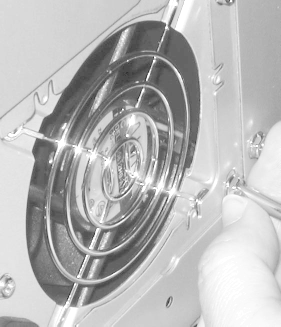
 |
Many power supplies are adjustable
for 110/115 volts or 220/230 volts. Make sure to set the power supply
for the correct input voltage. If the voltage selection switch is set
to 220/230V and your mains power is 110/115, the system
won't boot, but no damage occurs. But if the voltage
selection switch is set to 110/115 and your mains power is 220/230,
you will destroy your motherboard, processor, memory, and drives the
moment you apply power to the system. Some power supplies
automatically sense input voltage and adjust themselves accordingly.
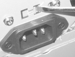
If there is no voltage selector switch on your power supply, check
the manual rather than assuming that it is auto-sensing. (See Figure 28-6.)
|
|
 If
it has not already been done, install the power switch and connect
the main power
cables.
Traditional AT power supplies for desktop cases have a built-in
power switch (the "big red paddle
switch"), and require no configuration. Power
supplies designed for AT mini-tower cases have four main power leads
(usually blue, white, brown, and black) with spade lug connectors
that attach to the power switch on the front of the case. If they are
not already connected, connect them, being very careful to orient
them properly. Note that these wires carry mains voltage; connecting
them incorrectly may short the power supply and destroy it. Use
electrical tape to insulate each of the four connections. In
ATX
cases, the power switch has only one light-gauge two-wire cable
coming from it. You will connect this cable to the power switch
header pins on the ATX motherboard during a later assembly step.
If
the case has an LED to indicate CPU speed, change the jumpers on the
back of the LED assembly to cause it to display the proper CPU speed.
This step is entirely optional, because the LED display is
informational only and has no effect on system operation. We have a
550 MHz Pentium III system that still displays the CPU speed as 6
MHz, the default for that case, because we lost the instructions that
tell us how to change the display. Install supplemental case
fan(s),
if necessary. Not all cases can accept supplemental fans, and not all
systems require them. Minimally configured systems with basic
processors ordinarily do not require supplemental fans. Heavily
loaded systems—those with multiple hard drives, fast (or dual)
processors, most or all expansion slots occupied, and so
on—should have supplemental fans installed. Fans are available
in several sizes, including 60, 70, 80, 90, and 120 mm. Some cases
have multiple fan mounting positions that require different fan
sizes. (See the sidebar Ensuring Proper Airflow.)
|
If you install supplemental fans, make
certain they blow the proper direction—aiding the main power
supply fan rather than fighting it. We have seen processors destroyed
by overheating in tightly sealed systems with supplemental fans
blowing the wrong direction.
Standard AT power supplies and some ATX power supplies blow out
from the power supply, exhausting air from within the case. For these
systems, install supplemental fans to push air into the case. Some ATX
power supplies suck air into the power supply, pressurizing the case.
For these systems, install supplemental fans to draw air out of the
case.
Most supplemental fans
can be installed to push air either direction, either by simply
reversing the fan assembly or by throwing a small switch on the fan
itself. Some cases are supplied with supplemental fan(s) installed.
Do not assume that these fans are necessarily configured correctly.
We have seen more than one such case with power supply and
supplemental fans both configured to push air into the case, or both
configured to draw air out of it. In a typical case, which has many
openings for airflow, this may not be a problem. But in a well-sealed
case, where the only airflow is through the fans, having the fans
working against each other can result in rapid overheating.
|
Install the feet on the case. Feet
are usually plastic devices an inch or so in diameter and a
quarter-inch thick. They may be secured to the case bottom with a
bolt and nut, with small plastic spreaders that are inserted from
inside the case, or simply with peel-and-stick adhesive. In all
cases, the feet are designed to prevent scarring of the surface that
the case rests upon. Some cases have vents in the bottom of the case,
and must have the feet installed for proper cooling. Most
ATX
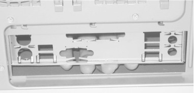
cases are supplied with a standard I/O template already in place, which
may or may not be suitable for your motherboard. Remove the
motherboard from its anti-static bag and compare the I/O panel on the
back of the motherboard with the installed template, as shown in
Figure 28-7. If the template that comes with the
case is appropriate for the motherboard, proceed to the next step.
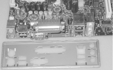
The Antec SX840 case comes with a standard I/O template installed,
but the holes are in the wrong locations for the Intel D845WNL
motherboard. That means we need to remove the I/O template that came
with the case and install the I/O template that was supplied with the
motherboard. To remove a template, press gently from the outside of
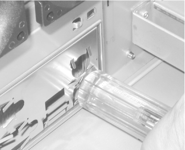
the case until the template snaps out. Some templates seat very
snugly, so you may need to use a small screwdriver to pry one edge
loose before you can snap the template out, as shown in Figure 28-8. Be careful not to bend the template as you
remove it. They are made of thin metal that bends easily, and you may
want to keep the standard template in case you ever want to install a
different motherboard in this case.
Install the new I/O template supplied with the motherboard from
inside the case, and press gently toward the outside of the case
until the template snaps into place, as shown in Figure 28-9. I/O templates can be difficult to install,
because they are made of easily bent metal and yet may require
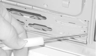
substantial pressure to seat. We generally get one edge aligned
properly and then press gently until the template seats. If you are
sure the template is aligned but cannot get it to seat, use the
handle of a screwdriver on alternate corners until you feel the
template snap into place, as in Figure 28-10. If you
do not have the correct I/O template, contact the motherboard or case
manufacturer to obtain one. Running the system without an I/O
template installed risks disrupting air flow.
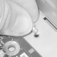
 Lay the motherboard flat in the case to determine which positions in
the motherboard tray require standoffs. Screw brass standoffs into
those positions, and verify that each motherboard mounting hole has a
corresponding standoff installed. Also verify that no extra standoffs
are installed, which might short the motherboard. Some cases use all
mounting holes; others use a combination of holes and slots. If yours
uses slots, lay aside the proper number of white nylon standoffs,
which you will later snap into the bottom of the motherboard for each
slotted position. Don't do that now, however,
because it prevents the motherboard from lying flat while you install
the CPU and RAM. If you need to remove a nylon standoff from the
motherboard, use your needle-nose pliers to squeeze the prongs on the
front side of the motherboard gently while pulling from the back side
of the
motherboard.
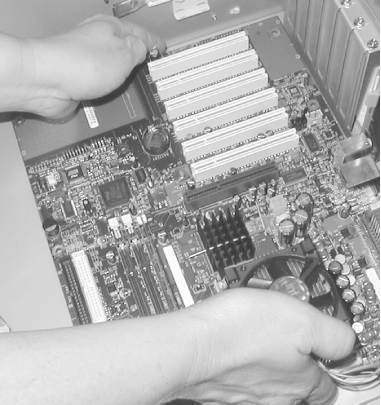
After you have installed a brass standoff spacer for each motherboard
mounting hole (Figure 28-11), slide the motherboard
into position and verify that all mounting holes line up with the
standoff spacers (Figure 28-12).
Don't install any screws yet, though. We still need
to install the processor and memory, and that's much
easier to do with the motherboard outside the case.
|


