|
|
|
5.2 Database Diagram DesignerThe database diagram designer window allows a considerable amount of information about a database's structure to be presented in one place. A single diagram can show many tables and the relationships among them. It also allows all of the items it displays to be edited. You can open the diagram designer with the Server Explorer, by expanding a database's Database Diagrams node and double-clicking on any existing diagrams. Adding a new diagram using the context menu will also show the diagram designer. Figure 5-6 shows a diagram representing certain
tables from the Northwind sample database. It shows all of the column
names in each of the tables present on the diagram and indicates
which columns form the primary key by annotating them with a key
graphic. The relations have all been shown, with the direction
indicated—the key indicates the table containing the primary
key, and the infinity sign ( Figure 5-6. Database diagram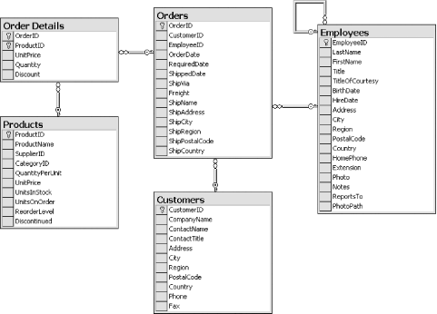 You can add new relations by dragging from a column in one table to a column in another table. This will cause the Create Relationship dialog to be displayed. The Create Relationship dialog is almost identical to the Relationships tab of the property pages, described later. At the bottom-right corner of the diagram window is an icon with crossed arrows, as Figure 5-7 shows. If you click and hold down the left mouse button on this icon, a "map" of the entire diagram will be displayed, as Figure 5-8 shows. Figure 5-7. Database diagram navigation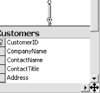 Figure 5-8. Database navigation map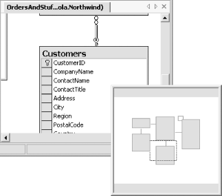 A dotted rectangular outline will be displayed on the map to represent the part of the diagram that is currently visible in the window. You can move this rectangle around while the mouse button is depressed in order to choose the part of the diagram you would like to look at. When you release the mouse button, the diagram window will display the chosen portion of the overall database diagram. Figure 5-9 shows the two context menus for the diagram designer. The one on the left is shown if you right-click on an empty area, and the one on the right is the context menu for a table. You can use these to create, modify, and delete tables through the diagram editor. You can add and remove columns and choose which columns form the primary key. If you want to include all of the tables related to a particular table, you can select the Add Related Tables item. The Relationships..., Indexes/Keys..., Check Constraints..., and Property Pages menu items all show the database properties pages dialog, which is described in Section 5.3. Figure 5-9. Diagram designer context menus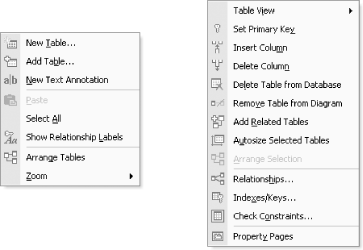 Figure 5-10. Table View menu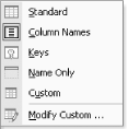 Figure 5-10 shows the Table View submenu of the table context menu. This allows you to select the way in which the table is presented in the diagram. The default is the Column Names view, which can be seen in Figure 5-6. The remaining view types are all illustrated in Figure 5-11. The Standard view is the same one that is used in the table designer. The Keys view shows only columns that act as keys. The Name Only view shows no columns at all, and the Custom view allows you to choose which information is shown about each column. You select the information to be shown by choosing Modify Custom... from the context menu. Figure 5-11. Table views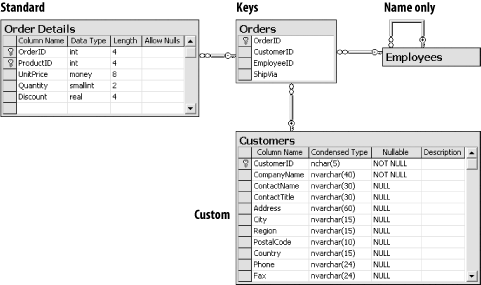 Because the diagram view shows information about multiple tables, its functionality overlaps with other designer views. (In fact, all of the modifications to the database's structure that the diagram designer allows can also be achieved through other means, either with other designers' views or with property pages—the diagram view is provided merely for convenience.) So if you change two tables in a diagram and then save your changes back to the database, Visual Studio .NET will inform you that it needs to save the two tables you modified as well as the diagram. |
|
|
|