28.3 Step 3: Install the Processor
Before you begin processor
installation,
place the motherboard flat on a firm surface, padding it with the
anti-static foam or bag supplied with it. Installing the CPU (and
memory) may require substantial force, so it's
important to ensure that the motherboard is fully supported to avoid
cracking it.
 |
We're installing a Socket 478 Pentium 4 processor,
so the instructions and illustrations in this section refer
specifically to that processor. If you're installing
a different processor, see Chapter 4 for more
detailed information.
|
|
To install the processor, take the
following steps:
Remove the processor from
its packaging and examine it closely to make sure that no pins are
bent. A new processor should never have bent pins. If one or more
pins are bent, that's certain proof that you were
sold a used or repackaged processor. Do not attempt to straighten
bent pins. Return the processor and insist on a replacement processor
in original factory shrinkwrap. The processor fits a Zero Insertion Force (ZIF) socket on the
motherboard. To prepare the socket to receive the processor, lift the
small lever on one side of the socket to the vertical position.
Examine the socket to determine
which corner is pin 1. pin 1 may be indicated by a small diagonal
cutout on the socket, by a dot or arrow, by a number 1 printed on the
socket or motherboard itself, or by other similar means. Once you
have located pin 1 on the socket, locate pin 1 on the processor,
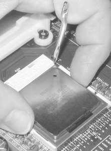
which is also marked clearly. Carefully align the processor with the socket, making sure that
pin 1 on the processor corresponds to pin 1 on the socket, and then
drop the processor into place, as shown in Figure 28-13. We say
"drop" rather than
"press" because the processor
should seat fully in the socket with little or no resistance
(that's why it's called
"Zero Insertion Force"). If you
encounter resistance, either the pins are misaligned or the ZIF lever
is not fully vertical. Don't force the processor
into the socket, because those tiny pins are very easy to bend, which
effectively destroys the processor. When the processor is seated
properly, its bottom should be flush against the top of the socket.
 With the processor fully seated, pivot the ZIF lever down until
it is parallel to the motherboard to lock the processor into place
(Figure 28-14). You may encounter resistance while
closing the lever, which is normal. Continue pressing the level down
until it snaps into place. Don't press too hard,
though. If the lever seems not to want to seat, you may have the
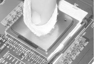
processor misaligned. 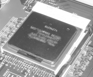 Before installing the heatsink/fan unit, use a paper towel to
polish the top of the processor to a mirror-like surface to remove
fingerprints and other residue (Figure 28-15).
Intimate contact between the processor and heatsink is critical to
ensure proper cooling. Even a fingerprint can interfere with heat
transfer.
 Retail-boxed Intel Pentium 4 processors
include a heatsink/fan unit and a pre-measured amount of
thermal
compound in a syringe. After you have polished the top of the
processor, use the supplied syringe to deposit the full amount of
supplied thermal compound in a small pile at the center of the
processor, as shown in Figure 28-16. Although it
appears that using all of the supplied thermal compound will make a
mess, you need to apply all of it to ensure proper cooling. 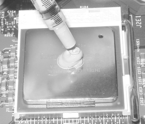 Lower the heatsink/fan unit gently into
position. Keep the heatsink as level as possible as you lower it into
contact with the processor (Figure 28-17). The goal
is to press the heatsink gently into place, thereby spreading the
thermal compound evenly over the surface of the processor to ensure
good heat transfer. If you tilt the heatsink as
you're moving it into place, most of the thermal
compound may be shifted to one side of the processor. When the
heatsink/fan unit is properly in place, it should be sitting level
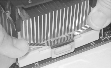
within the heatsink retention mechanism on the motherboard. 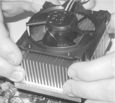 The heatsink/fan unit includes two
spring-steel retaining brackets that clamp the heatsink into tight
contact with the processor. Align each bracket so the central hole
fits over the corresponding tab on the heatsink/fan retention
mechanism, and then use both thumbs to press the two ends of the
retaining bracket until they snap into place against the heatsink
retention mechanism (Figure 28-18). It may require
substantial force to seat the bracket, so don't be
afraid to press hard. With some brackets, it's
easier to seat one side first while it's not under
tension and then press down the opposite side until it snaps into
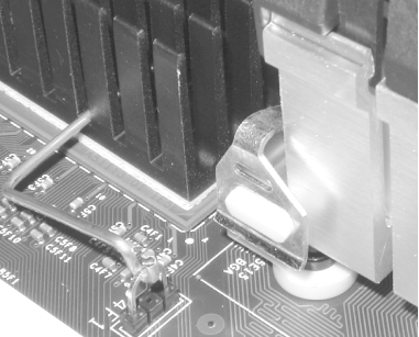
place. Make certain that both ends of both brackets are secured. You
don't want the heatsink/fan to come loose,
particularly if the motherboard is mounted vertically (Figure 28-19).
 The Pentium 4 CPU fan connects to a motherboard power header.
Most motherboards, including the D845WNL, include two or more such
power headers, but those headers are not fully interchangeable. All
of them supply the same voltage on the same pins, and any can be used
to power any fan, but the CPU fan header is designed to report the
speed of the CPU fan to the motherboard, where that information can
be used by a hardware monitoring utility. Connect the CPU fan header
to the specific motherboard power header intended for it. Other
motherboard power headers can also report fan speeds to the
motherboard, and are intended to power supplemental chassis fans.
(See Figure 28-20.) 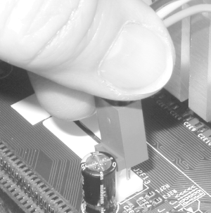
|


