28.5 Step 5: Prepare Drives for Installation
Several steps may be required before
installing some drives, including setting configuration jumpers,
installing mounting hardware, and installing supplemental cooling.
Some of those steps are difficult or impossible to perform after the
drive is installed in the system, so plan ahead. If you are
installing several drives, make a written plan of how each drive
needs to be configured to ensure that there are no conflicts. As you
configure each drive, check what you're doing
against the list and mark off each drive as you finish it.
 |
Many people find it helpful to label each drive with its function and
settings, e.g., ID-0, ID-1, and so on for SCSI drives, and Primary
Master, Primary Slave, Secondary Master, and Secondary Slave for
ATA/ATAPI drives. If you later upgrade the system, visible labels
eliminate the need to remove drives to examine their settings.
|
|
In turn, remove each drive from its
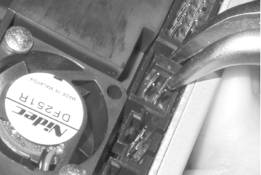
packaging and set jumpers as necessary to configure it (Figure 28-23). Leave unused jumper blocks connected to only
one pin, which has the same effect as removing the jumper block
entirely, but leaves that block conveniently available for future
use.

- IDE/ATAPI drives
-
For each
drive, set the jumper to designate the drive as Master, Slave, Only,
or Cable Select, as appropriate. Some ATAPI drives, particularly tape
drives, have jumpers to set other options, such as read-while-write
or hardware compression. Set these jumpers as recommended by the
documentation. A basic system uses one hard disk set as Primary
Master and one CD-ROM, CD-RW, or DVD-ROM drive as Secondary Master.
If your system has more IDE/ATAPI devices, see Chapter 14 for more information.
- SCSI drives
-
Some SCSI
drives require setting jumpers or DIP switches to specify a unique
SCSI ID for that drive and whether or not it is terminated. By
convention, the SCSI host adapter is assigned SCSI ID 7. ID 0 is
reserved for the boot hard disk, and ID 1 for a secondary hard disk.
IDs 2 through 6 are available for use by other devices such as tape
and optical drives. Make sure that the last physical device on each
SCSI bus (and only the last device) is terminated. For most drives,
you enable termination by setting a jumper or DIP switch, but some
drives use a small resistor pack instead. Many SCSI drives have
numerous other settings, e.g., parity, termination power, and delayed
motor start. Set jumpers for these options as recommended by the
documentation. If the host adapter and drives are SCAM (SCSI
Configured AutoMagically) compliant, SCAM sets ID and termination
automatically, but it does no harm to set parameters manually even on
a SCAM-compliant system.
- Floppy disk drives
-
Standard floppy disk drives require no configuration.
Decide where to mount each drive, considering the following issues:
- Convenient access
-
Place the externally accessible drives you will use most often where
it is easy to reach them. For example, for a tower unit that will sit
on the floor, place the CD drive in an upper drive bay.
- Drive spacing
-
If you have more drive bays than drives, use that extra space to
separate the drives, which improves cooling and makes it easier to
connect cables or change jumpers.
- Heat production
-
Some drives, such as CD writers and high-speed hard drives, generate
a lot of heat—hard drives constantly and CD burners
intermittently. Heat rises, so install heat-producing drives above
other drives whenever possible. This system has only an IDE hard
drive and a CD writer, so drive placement is not critical.
- Cable routing
-
We've learned this one the hard way more than once.
Make sure your cables will reach the positions where you install the
drives. This is usually not an issue with desktop or mini/mid-tower
cases, but with a full-tower case it's easy to
install two drives that must share the same cable so far apart that
the cable won't reach. It's also
less a problem with SCSI cables than with IDE cables, which are
limited to 18". Take care even with SCSI, however. You may find that
your SCSI cable is more than long enough, but the drive connectors
are too close together to span two drives installed far apart.
- Physical stability
-
If possible, avoid installing many heavy drives high in the case. The
concern is not so much to prevent the case from tipping, because most
cases are very stable. But tower systems with many heavy hard drives
(and the power supply) all installed near the top of the case are
very awkward to manipulate because all the weight is at one end.
If the drive is 3.5" form factor and will be installed in a
5.25" bay, install the drive in a chassis adapter.
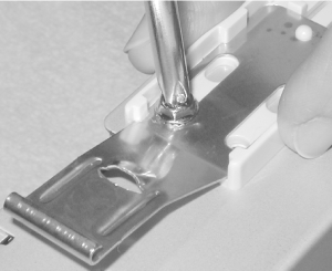
Attach any required mounting hardware, such as drive rails, to the
drive. Note that some cases have multiple locations where drives can
be installed that use different mounting methods, so
it's important to decide where each drive will be
mounted before you attach the mounting hardware to it. In some cases,
drives are mounted directly to the chassis by driving screws through
holes in the chassis and into the drive. In other cases, including
the Antec SX840, mounting rails are used. You will usually find that
the drive can be secured by four or more screws on each side. We
normally use only two on each side—one front and one
back—unless the system will be moved frequently or is subject
to vibration. In that case, we use four screws on each side and
secure them with a dab of nail polish to prevent them from vibrating
loose. That's not necessary for this system, so we
mount the rails with two screws per side. If your case uses plastic
drive rails, make sure that at least one screw connects the drive
itself to the metal grounding strap on the rail. (See Figure 28-24.)
 For high-performance disk drives (some 7,200 RPM and all 10,000 and
15,000 RPM drives), install supplementary drive cooling to prevent
overheating. Small supplementary fans (so-called
"drive coolers") are adequate for
most 7,200 RPM drives. For 10,000 and 15,000 RPM drives, we recommend
using a full bay cooling unit like the PC Power & Cooling
Bay-Cool, which integrates a 3.5" to 5.25" chassis adapter with two
fans and a filtered inlet. The Seagate Barracuda ATA IV drive is a
very cool running drive, and requires no supplementary cooling.
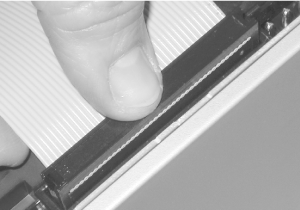
If
possible, connect the data cable to the drive while the drive is
still outside the case (Figure 28-25). If you install
the drive in the chassis first, it's much harder to
make sure the cable is aligned properly. If more than one drive will
connect to a cable, it's generally best to connect
the cable to the "difficult" drive
before you install it and make the connections to the more readily
accessible drives after they're installed in the
chassis. This system has only two drives, each of which has its own
cable, so we can install both cables before installing the drives.
When you install the cable, make sure the colored stripe on the cable
corresponds to pin 1 on the drive connector. Line the cable up,
making sure that it is not offset by a row or column of pins, and
then press it firmly into place. We'll connect the
power cable later.

 |
Use the proper ATA
cable for the type of drive you are
installing. Optical drives, tape drives, and similar lower
performance drives can use either a standard 40-pin, 40-wire ATA
cable or a 40-pin, 80-wire Ultra ATA cable. For Ultra ATA hard
drives, use only an Ultra ATA cable. If you use a standard ATA cable,
the drive will operate, but will not provide its best
performance.
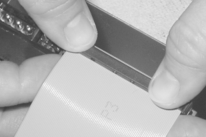
Make sure to connect the drive to the proper connector on
the cable (Figure 28-26). ATA cables have three
connectors. Two are grouped together toward one end, and are used to
connect drives. One end connector is widely separated from the other
two, and connects to the motherboard ATA interface. If
you're installing only one drive on the cable,
connect it to the end connector, leaving the middle connector unused.
|
|

|


