28.8 Step 8: Install the Motherboard
Slide the
motherboard
into position, verifying that each motherboard mounting hole aligns
with its brass standoff, that each nylon standoff slides properly
into the corresponding slot on the motherboard tray, and that the I/O
connectors on the rear of the motherboard align properly with the I/O
template (or the access holes in the
chassis).
While maintaining continuous gentle pressure toward the rear of the
chassis to keep the motherboard
aligned with the mounting holes, insert one of the mounting screws,
but don't tighten it fully. Continue inserting
mounting screws loosely until all mounting holes are occupied.
Finally, tighten each mounting screw gently, as shown in Figure 28-30. Finger-tight is adequate.
We've seen people crack motherboards by applying too
much torque to the mounting screws.
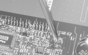 Make sure to install a motherboard mounting screw at every position.
In addition to securing the motherboard physically, these screws also
ground the motherboard to the chassis. Their positions are carefully
calculated by motherboard designers with grounding in mind. Leaving
one or more screw positions vacant can cause improper grounding,
which may cause instability or high RFI emissions.
If you have not already done so, connect the CPU fan to the
appropriate motherboard power header or to a spare drive power cable.
Connect the main power lead from the power supply to the motherboard.
For ATX systems, the main power connector is a single 20-pin keyed
connector, shown in Figure 28-31. The Main ATX Power
Connector is keyed, which prevents misconnecting the main power lead.
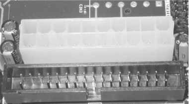
Note to the upper right of the main ATX power connector the
silk-screened label and solder points for the Auxiliary ATX Power
Connector (Figure 28-32). Although the Antec power
supply provides this connector, this variant of the D845WNL
motherboard does not require it, so we leave it unused. If your
motherboard has a connection point for the Auxiliary ATX Power
Connector, make sure to connect it as well as the Main ATX Power
Connector.
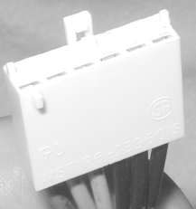
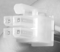
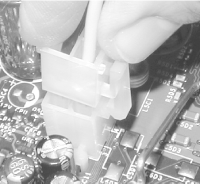
The Intel D845WNL motherboard requires the ATX12V Supplementary Power
Connector, shown in Figure 28-33. This
"P4 connector" supplies the
additional 12V current required by Pentium 4 motherboards. It is
keyed to prevent incorrect installation, and simply snaps into place,
as shown in Figure 28-34. All current Pentium 4
motherboards require this connector, and we think it likely that
future Pentium 4 motherboards will as well. If you forget to insert
the ATX12V Supplementary Power Connector, your Pentium 4 motherboard
will not boot.
 |
The Antec power supply we're using for this project
has a P4 connector. Older power supplies usually do not, even though
they may otherwise be capable of powering a Pentium 4 system. If
you're installing a Pentium 4 motherboard and the
existing power supply is not P4 compliant, you may be able to save
the cost of replacing the power supply by buying an adapter cable.
These cost $5 or so, and are sold by PC Power & Cooling and most
computer stores. They connect to a drive power cable on one end and
have the connector shown in Figure 28-33 on the
other. Pentium 4 motherboards don't care where they
get the extra 12V current, as long as they do get it.
|
|
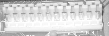
If you're working
on an older system, be careful. AT systems use two main power cables,
each with a 6-pin keyed connector (often labeled P8 and P9), which
connect to one 12-pin connector strip on the motherboard, shown in
Figure 28-35. It's possible to swap
the positions of these cables, which can destroy a motherboard, so be
careful which you connect where. For nearly all AT power supplies,
the black wires will be toward the center when both connectors are
installed properly, but we have encountered AT power supplies with
nonstandard wire colors. Verify connector orientation with the
documentation for your power supply and motherboard rather than
making assumptions. Note that some power supplies have both AT and
ATX power connectors, as do some motherboards.
 ATX motherboards organize all I/O connectors in a block
that matches the I/O template on the
rear. AT motherboards use a permanently mounted keyboard connector
that aligns with the keyboard hole in AT cases, but other I/O
ports—serial, parallel, USB, and so on—exist only as
groups of header pins on the motherboard. Those I/O ports are made
accessible on the rear panel of the case by installing port
extenders, which are cables with a header-pin connector on
one end and the appropriate I/O connector on the other. Some port
extenders are normally supplied with the motherboard, but many AT
motherboards do not include port extenders for all ports. For
example, the extenders for Serial 2 and USB are often optional items.
These port extenders are relatively standard items. If
you're missing any, you can buy them for a few
dollars at any well-stocked computer store.
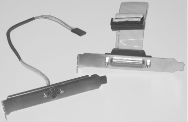
Figure 28-36 shows two typical port extenders for an
AT motherboard. On the left is a PS/2 mouse connector, and on the
right is a DB25 serial port connector.
To install a port extender, align the header-pin
connector with the appropriate set of header pins on the motherboard,
making sure that pin 1 corresponds to the red stripe on the cable,
and press down until the connector seats. Most port extenders have
the external connector mounted on an expansion slot bracket. The case
may have more expansion slot cutouts than the motherboard has
expansion slots. If so, mounting the port extender in an expansion
slot cutout costs nothing. If your system has the same number of
expansion slots and cutouts, mounting the port extender in an
expansion slot cutout wastes that expansion slot. Most AT cases
contain several precut holes for DB9, DB25, and other connectors. On
better cases, the covers for these holes are secured by screws. On
inexpensive cases, the covers are die-cut and need to be twisted out
with needle-nose pliers. Remove the covers for the ports you need to
extend. Remove the port extender connector from the slot bracket and
mount it directly to a matching cutout in the rear panel of the
chassis.
|


