28.9 Step 9: Connect Cables to the Motherboard
All systems require connecting
various cables to the motherboard. These include:
Cables that connect floppy, hard, and optical drives to embedded
motherboard interfaces.
Cables for miscellaneous functions, such as connecting audio out on
the rear panel of a CD-ROM drive to the audio header on the
motherboard, or connecting a CPU fan to a power header on the
motherboard.
Cables that connect front-panel switches (power,
reset, keylock, etc.) and indicators (drive activity, power on,
speaker, etc.).
Supplementary case fans, which may connect to the motherboard or to
power supply connectors.
It's usually easier to connect these cables before
you start installing expansion cards. Proceed as follows:
Connect the drive data cables from the back of each drive to the
appropriate connector on the motherboard, making sure to align
pin 1 properly on both the drive
and controller. Typical systems have at least two such cables: a
34-wire ribbon cable connecting the floppy disk drive to the FDD
controller interface on the motherboard, and an IDE cable connecting
the hard drive and CD- or DVD-ROM drive to the primary IDE interface
connector on the motherboard. If the system has more than two IDE
devices, or if you put the hard drive and optical drive on separate
channels, you will also need to connect a second IDE cable from the
additional device(s) to the secondary IDE interface connector on the
motherboard. If the system has SCSI devices installed and the
motherboard has an embedded SCSI host adapter, also connect cable(s)
from the SCSI device(s) to the SCSI connector(s).
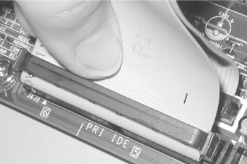
If you are connecting devices to both ATA interfaces, make sure to
connect each cable to the proper interface. Figure 28-37 shows the Ultra ATA (40-pin, 80-wire) cable
from the hard drive being connected to the primary interface. Visible
behind that cable is a standard (40-pin, 40-wire) ATA cable connected
to the secondary interface.
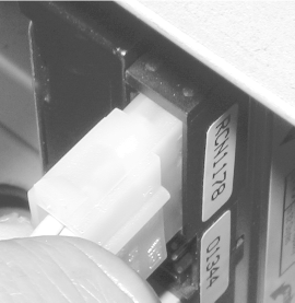
 If it has not already been done, connect a power cable from the power
supply to the power connector on the rear of each drive (Figure 28-38). If you have more drives than power leads,
use a splitter to allow two drives to share one power lead. Splitters
may be provided with the case and power supply, or may be purchased
inexpensively at any computer store. Although it's
probably not a major issue, the power leads use relatively small
gauge wires, so we try whenever possible to connect high-draw devices
like fast disk drives and CD burners to separate power leads. When
you insert the power connector, press hard enough to make sure it
seats fully. This sometimes requires substantial pressure, and we
have seen systems with "failed"
drives that were caused by the power connector falling out.
 Connect any supplementary cables required, such as CD audio, CPU fan,
hardware management, temperature sensors, Wake-on-LAN, chassis
intrusion, video-source line-in, aux line-in, telephony, and so on.
Refer to your motherboard manual for details.
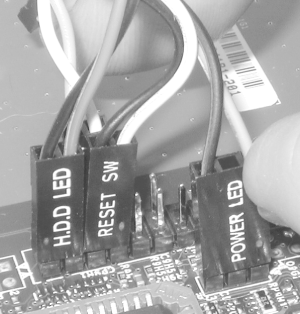
Connect the front-panel cables to the header-pin connectors on the
motherboard, which are usually arranged in a block near the front
edge (Figure 28-39). Typically these connectors will
include: power switch (ATX only), reset switch, hard disk activity
LED, power-on LED, and speaker. Depending on the motherboard and
case, you may also have connectors for keylock, Infrared port, and
perhaps a secondary drive activity LED.

Connectors may or may not be labeled. If not, you will have to trace
each wire back to the front panel to determine which connector is
which. Most connectors are two-pin. For those that connect to
switches, polarity is immaterial. For those that connect to LEDs,
polarity may or may not matter. Best practice is to orient the
connector for proper polarity. Most cases use the black wire of each
pair for ground. The ground pin for each connector may or may not be
marked on the motherboard. If not, refer to the manual.
If your case has a supplementary cooling fan or fans, connect the fan
power lead(s) to the motherboard or to a spare power supply power
connector, as appropriate.
|
One problem arises more often than it should. Sometimes, the pinouts
on the motherboard do not match the pinouts on the connector. Intel
and other manufacturers are attempting to standardize the arrangement
and pinouts for front-panel connectors, but many motherboards and
cases still use their own arrangements. For example, we have
encountered motherboards that have all four pins present for a
standard four-position speaker connector (which actually needs only
two wires anyway). If the four-position connector on the speaker wire
has one position blocked, as is frequently the case, it is impossible
to slide that connector onto the pins on the motherboard without some
surgery. Sometimes you can penetrate the blocked position with a
needle or sharp awl, or remove the plastic block with a small
screwdriver or your needle-nose pliers. If that
doesn't work, you may be able to bend the extra pin
far enough out of the way to slide the connector onto the three
remaining pins. Other times, you must use your nippers to cut off the
extra pin.
Even that's not the worst case. We have encountered
some combinations of case and motherboard with oddball pinouts that
are impossible to match up. For example, the case provides a single
four-position connector that incorporates the Power LED and Reset
Switch, whereas on the motherboard these functions are separated by
several pins. In such cases, the only solution is to use a razor
knife carefully to split the multi-position connector into separate
one- or two-position connectors.
Some cases (oddly enough, usually the very inexpensive ones) avoid
this problem entirely by using one-position connectors on all wires
that lead to front-panel switches and indicators. That is, each wire
is completely independent of every other wire, which allows you to
connect individual wires in any fashion the motherboard requires.
Dealing with individual connectors is clumsy and time-consuming, but
it does provide complete flexibility.
The best way to avoid a situation like this is to verify ahead of
time that the front-panel header pins on the motherboard match the
connectors on the case.
|
|


